
Multiple Choice
An inductor, a capacitor, and a resistor are in series with a AC source. If the capacitor is , the inductor is and the resistor is . what is the impedance?
1284
views
 Verified step by step guidanceVerified video answer for a similar problem:
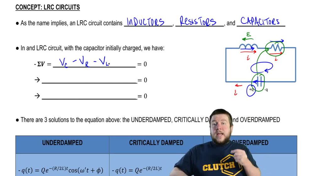
 09:40
09:40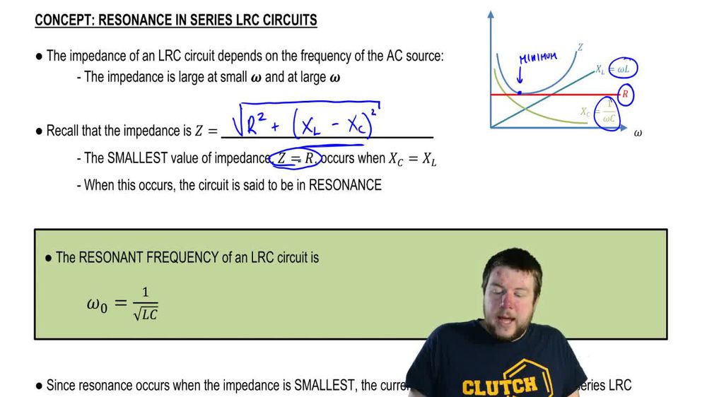 05:23
05:23 08:02
08:02