 Back
BackAnalyzing Ammeter and Voltmeter Readings in a Multi-Loop Circuit
Study Guide - Smart Notes
 Tailored notes based on your materials, expanded with key definitions, examples, and context.
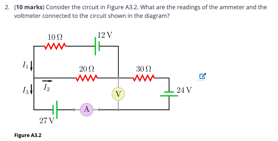
Q2. What are the readings of the ammeter and the voltmeter connected to the circuit shown in Figure A3.2?
Background
Topic: DC Circuits – Kirchhoff’s Laws
This question tests your ability to analyze a multi-loop circuit using Kirchhoff’s Current Law (KCL) and Kirchhoff’s Voltage Law (KVL). You are asked to determine the current measured by the ammeter and the voltage measured by the voltmeter in the given circuit.
Key Terms and Formulas
Kirchhoff’s Current Law (KCL): The sum of currents entering a junction equals the sum of currents leaving the junction.
Kirchhoff’s Voltage Law (KVL): The sum of the potential differences (voltage) around any closed loop is zero.
Ohm’s Law:
Step-by-Step Guidance
Assign current variables to each branch as shown in the diagram: (through the 10 Ω resistor), (through the 20 Ω and 30 Ω resistors), and (through the ammeter and 27 V battery).
Apply KCL at the top left junction: .
Write a KVL equation for the left loop (containing the 27 V and 12 V batteries, 10 Ω and 20 Ω resistors):
Write a KVL equation for the right loop (containing the 24 V battery, 20 Ω and 30 Ω resistors):
Or, if the current splits, carefully consider the direction and sum of voltage drops and rises.
Express the ammeter reading as the current and the voltmeter reading as the voltage across the 30 Ω resistor (or as specified by the diagram).
Try solving on your own before revealing the answer!
Final Answer:
The ammeter reads the value of (in amperes), and the voltmeter reads the voltage across the 30 Ω resistor (in volts). By solving the simultaneous equations from KCL and KVL, you can find the exact values for these quantities.
Remember to check the direction of each current and the polarity of each voltage source when applying the laws.
