 Back
BackChapter 12: Torque and Rotational Motion – Study Notes
Study Guide - Smart Notes
 Tailored notes based on your materials, expanded with key definitions, examples, and context.
Chapter 12: Torque
Overview
This chapter explores the causes of changes in rotational motion, focusing on the concepts of torque and angular momentum. It covers the factors influencing rotational motion, the conditions for rotational equilibrium, and the vector nature of rotation. Applications include free rotation, extended free-body diagrams, conservation of angular momentum, rolling motion, and the vector product.
Section 12.1: Torque and Angular Momentum
Definition and Physical Meaning of Torque
Torque is the measure of a force's ability to cause an object to rotate about an axis. It is the rotational analog of force in linear motion.
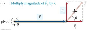
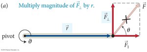
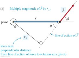
Torque (τ) is defined as the product of the force and the lever arm (perpendicular distance from the axis of rotation to the line of action of the force).
Only the component of force perpendicular to the lever arm causes rotation.
SI unit: Newton-meter (N·m).
Factors Affecting Torque
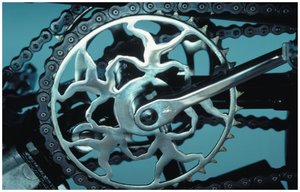
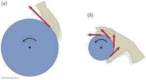
The effectiveness of a force in producing rotation depends on:
The magnitude of the force (F).
The distance from the pivot (r).
The angle at which the force is applied (θ).
The mathematical expression for torque is:
Examples: Seesaw and Lever Arm
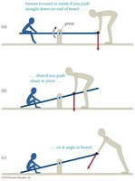
Applying force farther from the pivot increases torque. Force applied perpendicular to the lever arm is most effective.
Seesaw: Easier to lift a child by pushing at the end of the board, perpendicular to its surface.
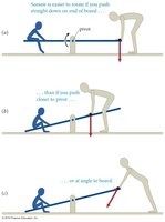
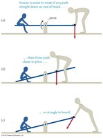
Balanced Torques and Rotational Equilibrium
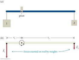
For an object to be balanced (in rotational equilibrium), the sum of torques must be zero:
General condition:
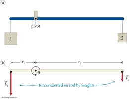
Perpendicular Force Component
Only the perpendicular component of force (F⊥) contributes to torque:
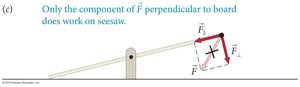
Calculating Torque: Two Methods
Using the perpendicular force:
Using the lever arm:
Sign of Torque
The sign of torque depends on the direction of rotation:
Counterclockwise torque is positive.
Clockwise torque is negative.
For stationary objects:
Section 12.2: Free Rotation
Center of Mass and Free Rotation
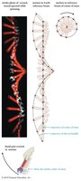
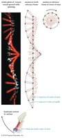
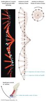
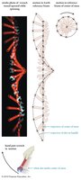
When an object rotates freely (not constrained by an axis), it rotates about its center of mass. The center of mass follows a trajectory consistent with free fall, while other points move in circles around it.
Objects thrown with spin rotate about their center of mass.
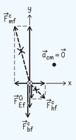
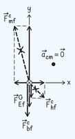
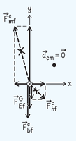
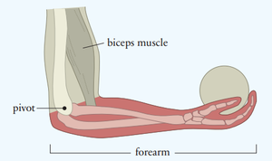
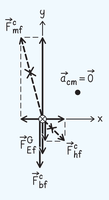
Section 12.3: Extended Free-Body Diagrams
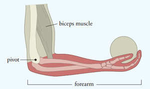
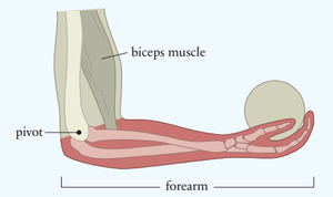
Constructing Extended Free-Body Diagrams
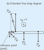
Extended free-body diagrams account for both translational and rotational forces. The procedure involves:
Draw a standard free-body diagram for the object.
Draw a cross-section in the plane of rotation.
Choose a reference point (pivot, center of mass, or any convenient point).
Draw vectors for all forces acting in the plane.
Indicate rotational acceleration (α) near the axis.
Section 12.4: The Vector Nature of Rotation
Rotation as a Vector Quantity
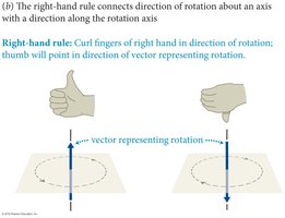
Rotational quantities such as angular displacement (Δθ), angular velocity (ω), and angular acceleration (α) are vectors. Their direction is determined by the right-hand rule:
Curl fingers in the direction of rotation; thumb points in the direction of the rotation vector.
Non-commutativity of Rotational Displacements
Unlike linear displacement vectors, rotational displacements do not commute (order matters). For small rotations, however, they approximately commute.
Section 12.5: Conservation of Angular Momentum
Newton’s Second Law for Rotation
For a particle constrained to move in a circle:
For rotational motion:
where I is the rotational inertia.
Angular Momentum and Rotational Impulse
Angular momentum (L) is given by:
Change in angular momentum is caused by external torque:
Rotational impulse (J) is the transfer of angular momentum from the environment:
Mechanical Equilibrium
An object is in mechanical equilibrium if both translational and rotational equilibrium are satisfied:
(translational)
(rotational)
Section 12.6: Rolling Motion
Kinematics and Dynamics of Rolling Motion
Rolling motion combines translational and rotational motion. For rolling without slipping:
The point of contact with the surface has zero instantaneous velocity.
Role of Static Friction
Static friction decreases the center-of-mass speed and acceleration.
It also causes the torque that gives rotational acceleration.
Section 12.7: Torque and Energy
Rotational Kinetic Energy
Torque causes rotational acceleration, changing rotational kinetic energy:
For objects in both translational and rotational motion:
Change in kinetic energy:
Section 12.8: The Vector Product
Vector Product (Cross Product)
The vector product combines two vectors to obtain a third vector perpendicular to both:
The magnitude is the area of the parallelogram formed by the vectors.
Relationship Between Translational and Rotational Dynamics
The table below summarizes the analogies between translational and rotational dynamics:
Translational | Rotational |
|---|---|
Force (F) | Torque (τ) |
Mass (m) | Rotational inertia (I) |
Acceleration (a) | Angular acceleration (α) |
Momentum (p) | Angular momentum (L) |
Summary
Torque is the rotational analog of force, causing angular acceleration.
Rotational equilibrium requires the sum of torques to be zero.
Objects in free rotation rotate about their center of mass.
Rolling motion combines translational and rotational motion, with static friction playing a key role.
Angular momentum is conserved in the absence of external torques.
The vector product is used to describe torque and angular momentum as vector quantities.
