 Back
BackChapter 19: Current, Resistance, and DC Circuits – Study Notes
Study Guide - Smart Notes
 Tailored notes based on your materials, expanded with key definitions, examples, and context.
Chapter 19: Current, Resistance, and DC Circuits
Current
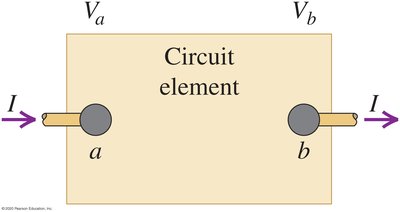
Electric current is the flow of electric charge through a conductor, typically measured in amperes (A). The direction of conventional current is taken as the direction positive charges would move, even though in most conductors, electrons (negative charges) are the actual charge carriers.
Definition: Current (I) is the rate at which charge (Q) flows through a surface.
Formula:
Unit: Ampere (A), where 1 A = 1 C/s
Example: If 2 coulombs of charge pass through a wire in 1 second, the current is 2 A.
Resistance and Ohm’s Law
Resistance is a measure of how much a material opposes the flow of electric current. Ohm’s Law relates the voltage across a resistor to the current flowing through it and its resistance.
Definition: Resistance (R) is the ratio of voltage (V) to current (I).
Formula:
Unit: Ohm (Ω)
Example: A resistor with R = 5 Ω and current I = 2 A has a voltage drop V = 10 V.
Electromotive Force (emf) and Circuits
Electromotive force (emf) is the energy provided by a source (such as a battery) per unit charge. It is not a force but a potential difference that drives current in a circuit.
Definition: emf (ε) is the total energy supplied per coulomb of charge.
Unit: Volt (V)
Example: A battery with emf of 12 V supplies 12 joules of energy per coulomb of charge.
Energy and Power in Electric Circuits
When charges move through a potential difference, energy is transferred and can be dissipated as heat or used to do work. Power is the rate at which energy is transferred or converted.
Work done on a charge: , where
Total charge in time interval:
Work done during :
Power delivered:
Alternative power formulas:
Unit: Watt (W), where 1 W = 1 J/s
Example: A device with 2 A current and 5 V potential difference dissipates 10 W of power.
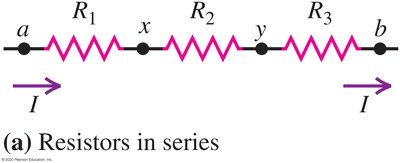
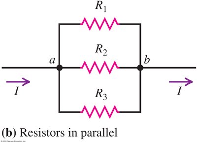
Resistors in Series and Parallel
Resistors can be connected in series or parallel, affecting the total resistance and current distribution in a circuit.
Resistors in Series
Current: The same current flows through all resistors:
Equivalent resistance:
Example: Three resistors of 2 Ω, 3 Ω, and 5 Ω in series have .
Resistors in Parallel
Voltage: The same voltage is across all resistors:
Equivalent resistance:
Example: Two resistors of 6 Ω and 3 Ω in parallel have .
Mixed Series-Parallel Networks
Some circuits combine series and parallel arrangements. Calculate equivalent resistance by reducing parallel and series groups stepwise.
Example: in series with a parallel combination of and :

Kirchhoff’s Rules
Kirchhoff’s rules are used to analyze complex circuits with multiple loops and junctions.
Junction Rule: The sum of currents entering a junction equals the sum leaving it.
Loop Rule: The sum of potential differences around any closed loop is zero.
Application: Used to solve for unknown currents and voltages in multi-loop circuits.
Electrical Measuring Instruments
Devices such as ammeters, voltmeters, and ohmmeters are used to measure current, voltage, and resistance, respectively.
Ammeter: Measures current; connected in series.
Voltmeter: Measures voltage; connected in parallel.
Ohmmeter: Measures resistance; often used with the circuit powered off.
Resistance-Capacitance (RC) Circuits
RC circuits contain both resistors and capacitors. They are important in timing and filtering applications.
Charging a capacitor: The voltage and current change exponentially over time.
Time constant:
Example: In an RC circuit with R = 1 kΩ and C = 1 μF, ms.
Equation for charging:
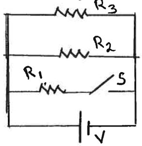
Example: Switches in Circuits
Switches can change the configuration of a circuit, affecting current and power distribution.
When a switch closes: It may add a parallel path, reducing total resistance and increasing current from the battery.
Power delivered by the battery: Increases if total resistance decreases.
Example: In a circuit with three resistors and a switch, closing the switch can change the current through and the total power output.
Summary Table: Series vs. Parallel Resistors
Connection Type | Current | Voltage | Equivalent Resistance |
|---|---|---|---|
Series | Same through all | Adds across each | |
Parallel | Adds across each branch | Same across all |
Additional info: These notes cover the essential concepts and formulas for DC circuits, including current, resistance, power, and resistor networks, as well as practical circuit analysis techniques.
