 Back
BackChapter 20: Magnetism – Structured Study Notes
Study Guide - Smart Notes
 Tailored notes based on your materials, expanded with key definitions, examples, and context.
Magnetism
Magnets and Magnetic Fields
Magnetism is a fundamental force arising from the motion of electric charges. Magnets possess two distinct ends called poles: the north pole and the south pole. The interaction between these poles determines the behavior of magnets.
Like poles repel each other, while unlike poles attract.
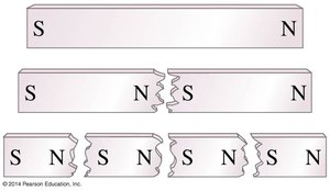
Cutting a magnet in half results in two smaller magnets, each with both a north and a south pole.
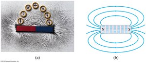
Magnetic fields are visualized using magnetic field lines, which always form closed loops.
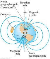
The Earth acts as a giant magnet, with its magnetic field resembling that of a bar magnet. The geographic North Pole is actually a magnetic south pole.
Example: The behavior of compass needles and the alignment of iron filings around a bar magnet demonstrate the presence and direction of magnetic fields. 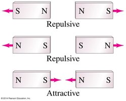
Electric Currents Produce Magnetic Fields
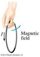
Electric currents generate magnetic fields, a phenomenon first observed in experiments with wires and compasses. The direction of the magnetic field produced by a current-carrying wire is determined by the right-hand rule.
When current flows through a wire, it creates circular magnetic field lines around the wire.
The right-hand rule: If you wrap your right hand around the wire with your thumb pointing in the direction of the current, your fingers curl in the direction of the magnetic field.
Example: Compasses placed around a current-carrying wire align tangentially to the magnetic field lines. 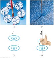
Force on an Electric Current in a Magnetic Field; Definition of B
A current-carrying wire placed in a magnetic field experiences a force. The direction of this force is given by the right-hand rule, and its magnitude depends on several factors.
The force is perpendicular to both the current and the magnetic field.
The magnitude of the force is given by: where I is the current, \ell is the length of the wire in the field, B is the magnetic field strength, and \theta is the angle between the wire and the field.
The unit of magnetic field B is the tesla (T). 1 T = 1 N/(A·m). The gauss (G) is also used: 1 G = T.
Example: A wire carrying current placed between the poles of a magnet will experience a force perpendicular to both the current and the field. 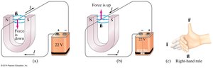

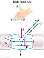
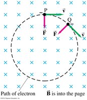
Force on Electric Charge Moving in a Magnetic Field
A moving electric charge in a magnetic field experiences a force, similar to the force on a current-carrying wire. The direction is determined by the right-hand rule.
The force is given by: where q is the charge, v is the velocity, B is the magnetic field, and \theta is the angle between velocity and field.
If the charge moves perpendicular to a uniform magnetic field, its path becomes circular.
The right-hand rule helps determine the direction of force for positive and negative charges.
Example: Electrons moving in a magnetic field follow a circular path due to the perpendicular force. 
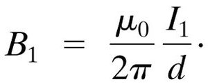
Magnetic Field Due to a Long Straight Wire
The magnetic field produced by a long, straight current-carrying wire decreases with distance from the wire. The field is given by:
Where \mu_0 is the permeability of free space ( T·m/A), I is the current, and r is the distance from the wire.
Example: The field strength is stronger closer to the wire and weaker farther away. 
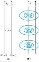
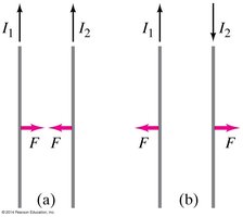
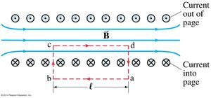
Force between Two Parallel Wires
Two parallel wires carrying currents exert forces on each other due to their magnetic fields. The nature of the force depends on the direction of the currents.
The magnetic field at wire 2 due to wire 1 is:
The force on a length \ell_2 of wire 2 is:
Parallel currents attract; antiparallel currents repel.
Example: Two wires carrying current in the same direction will move toward each other, while opposite directions cause repulsion. 
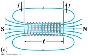
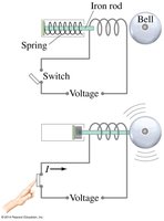
Solenoids and Electromagnets
A solenoid is a long coil of wire that produces a nearly uniform magnetic field inside when current flows through it. Inserting an iron core increases the field strength, creating an electromagnet.
The magnetic field inside a solenoid is: where N is the number of turns, I is the current, and \ell is the length.
Electromagnets are widely used in devices such as bells, motors, and relays.
Example: An iron rod inside a solenoid increases the magnetic field, making the electromagnet stronger. 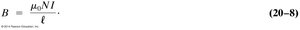
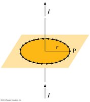
Ampère’s Law
Ampère’s Law relates the magnetic field around a closed loop to the total current passing through the loop. It is especially useful for calculating fields in symmetric situations.
Ampère’s Law: where the integral is taken around a closed path, and I_{enc} is the enclosed current.
Used for calculating fields in solenoids, toroids, and around wires.
Example: Calculating the field inside a solenoid using Ampère’s Law. 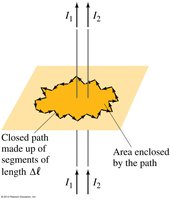
Torque on a Current Loop; Magnetic Moment
A current loop in a uniform magnetic field experiences a torque, which tends to align the loop with the field. The magnetic dipole moment quantifies the strength and orientation of the loop’s magnetism.
The torque is given by: where N is the number of turns, I is the current, A is the area, B is the field, and \theta is the angle.
The magnetic dipole moment:
Example: The torque on a loop is used in devices like galvanometers and electric motors.
Applications: Galvanometers, Motors, Loudspeakers
Several devices utilize the principles of magnetism:
Galvanometer: Measures electric current by the torque on a current loop.
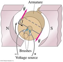
Electric motor: Converts electrical energy to mechanical energy using the torque on a current loop.
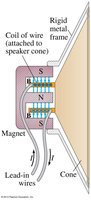
Loudspeaker: Uses the force on a current-carrying wire in a magnetic field to produce sound.
Example: The pointer in a galvanometer moves in response to current, and a motor’s armature rotates due to magnetic forces. 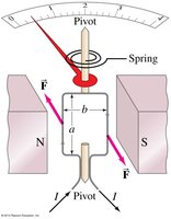
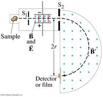
Mass Spectrometer
A mass spectrometer measures the masses of atoms by analyzing their motion in electric and magnetic fields. At a specific velocity, a charged particle is undeflected:
Particles with the same speed but different masses follow paths with different radii in the magnetic field.
Example: The radius of curvature in the spectrometer depends on the mass of the particle. 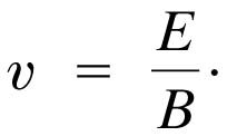
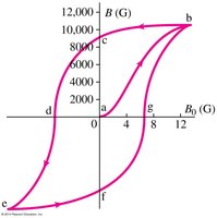
Ferromagnetism: Domains and Hysteresis
Ferromagnetic materials (e.g., iron, nickel) can be strongly magnetized. They consist of regions called domains, each with a uniform magnetic field.
Unmagnetized materials have randomly oriented domains.
Applying an external field aligns domains, magnetizing the material.
Magnetization can be retained or lost (demagnetized) by shock or heat.
The relationship between external and internal fields is complex, leading to hysteresis.
A hysteresis curve shows how the internal field changes as the external field is cycled.
Example: The process of magnetizing and demagnetizing a ferromagnetic material is visualized by domain alignment and hysteresis curves. 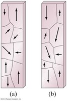
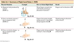
Summary Table: Right-Hand Rules
The right-hand rule is essential for determining directions in magnetic phenomena. The table below summarizes its application:
Physical Situation | Example | How to Orient Right Hand | Result |
|---|---|---|---|
Magnetic field produced by current | Wrap fingers around wire with thumb in direction of current | Fingers curl in direction of B | Direction of magnetic field |
Force on electric current in magnetic field | Fingers point straight along B, thumb along I | Thumb points in direction of force F | Direction of force |
Force on electric charge moving in magnetic field | Fingers point along velocity v, thumb along B | Thumb points in direction of force F | Direction of force |
Key Equations
Force on a current-carrying wire:
Force on a moving charge:
Magnetic field near a long straight wire:
Force between parallel wires:
Magnetic field inside a solenoid:
Velocity in mass spectrometer:
Additional info:
Magnetic field lines always form closed loops, never beginning or ending.
Ferromagnetic materials retain magnetization due to domain alignment.
Hysteresis is important in understanding magnetic memory and energy loss in materials.
