 Back
BackChapter 26: AC Electricity – Principles, Applications, and Safety
Study Guide - Smart Notes
 Tailored notes based on your materials, expanded with key definitions, examples, and context.
AC Electricity: Fundamentals and Applications
Introduction to Alternating Current (AC) and Direct Current (DC)
Electricity can be supplied as either direct current (DC) or alternating current (AC). DC maintains a constant direction and magnitude, while AC periodically reverses direction and varies in magnitude, typically in a sinusoidal pattern.
Direct Current (DC): Current flows in one direction only; voltage is constant.
Alternating Current (AC): Current reverses direction periodically; voltage oscillates sinusoidally.
Source of AC: Generated by rotating a coil in a magnetic field (e.g., electric generators).
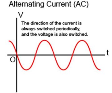
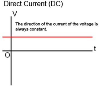
Example: Household electricity is supplied as AC, typically at 60 Hz in the United States.
Mathematical Description of AC Voltage and Current
The instantaneous emf (voltage) of an AC source is given by:
= peak emf (volts)
= period (seconds)
= frequency (Hz)
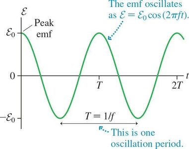
Example: In the US, wall outlets provide AC with a peak voltage of about 170 V and a frequency of 60 Hz.
Notation in AC Circuits
Capital letters denote constant quantities; lowercase letters denote time-varying quantities.
DC Ohm's Law:
AC Ohm's Law:
AC Circuits with Resistors
Resistor in an AC Circuit
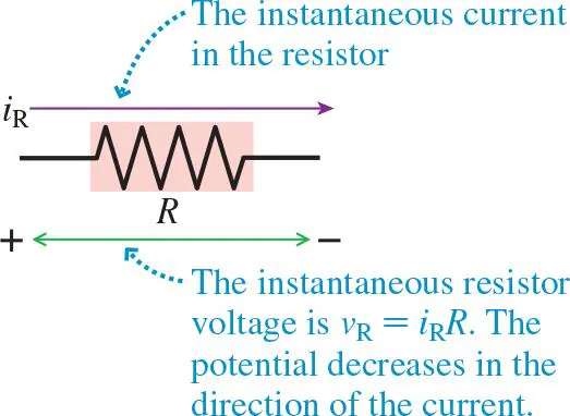
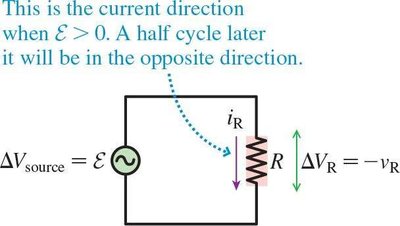
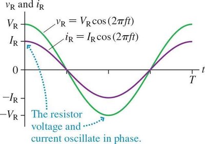
When a resistor is connected to an AC source, the voltage and current both oscillate sinusoidally and remain in phase.
Kirchhoff's loop rule applies:
Ohm's Law for AC:
Current and voltage reach their maxima and minima simultaneously (in phase).
Power in AC Resistor Circuits
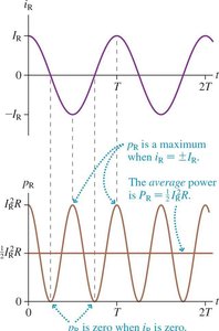
The instantaneous power dissipated in a resistor is:
Power oscillates at twice the frequency of the voltage/current.
Average power:
Root-Mean-Square (RMS) Values
To compare AC and DC values, we use the root-mean-square (rms) value, which represents the equivalent DC value that would produce the same power dissipation.
Average power:
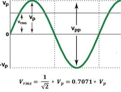
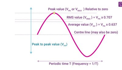
Example: For a US wall outlet, V, so V.
Transformers and Power Transmission
Principle and Construction of Transformers
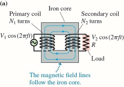
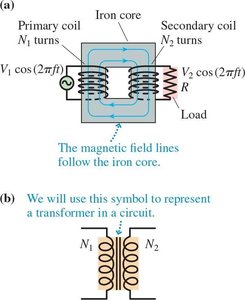
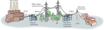
A transformer is a device that changes the voltage of AC electricity using electromagnetic induction. It consists of two coils (primary and secondary) wound on an iron core.
Primary coil: turns, connected to input voltage
Secondary coil: turns, output voltage
Operation requires AC (changing magnetic flux)
Transformer Equations
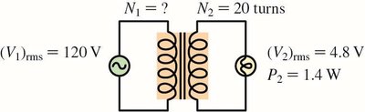
Voltage ratio:
Current ratio:
Power conservation (ideal transformer):
Step-up transformer: (increases voltage, decreases current)
Step-down transformer: (decreases voltage, increases current)
Power Transmission and Efficiency
Electricity is transmitted at high voltages to minimize power loss in transmission lines, which is proportional to the square of the current (). Transformers are essential for stepping up and down voltages for efficient transmission and safe usage.
Household Electricity and Safety
Grounding and Electrical Outlets
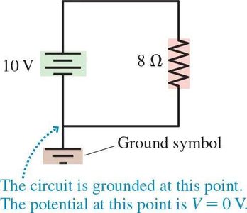
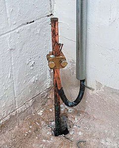
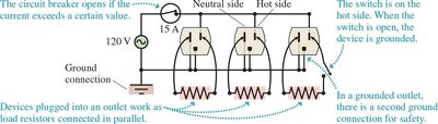
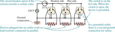
Grounding provides a reference potential (0 V) and a safe path for current in case of faults. Household outlets have a hot side (120 V AC) and a neutral side (grounded).
Circuit Protection: Fuses and Circuit Breakers
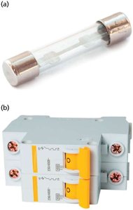
To prevent overheating and fire, circuits are protected by fuses or circuit breakers, which disconnect the circuit if the current exceeds a safe value.
Fuse: Melts and breaks the circuit when current is too high (must be replaced).
Circuit breaker: Electromechanical device that can be reset after tripping.
Parallel Wiring and Circuit Overload
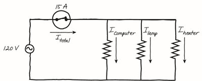
Household outlets are wired in parallel, so each device receives the full voltage. Overloading occurs when too many devices draw excessive current, risking tripping the breaker or causing fire.
Energy Consumption: Kilowatt-Hours
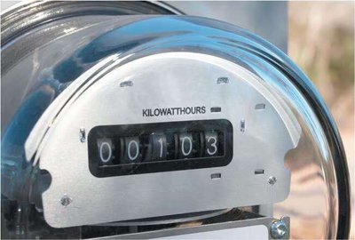
Electric energy usage is measured in kilowatt-hours (kWh):
1 kWh = J
Energy (kWh) = Power (kW) × Time (h)
Electrical Safety and Biological Effects
Physiological Effects of Electric Current
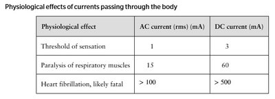
The danger of electric shock depends on the current passing through the body, not just the voltage. AC is generally more dangerous than DC for the same current.
Physiological effect | AC current (rms) (mA) | DC current (mA) |
|---|---|---|
Threshold of sensation | 1 | 3 |
Paralysis of respiratory muscles | 15 | 60 |
Heart fibrillation, likely fatal | > 100 | > 500 |
Body Resistance and Protective Measures
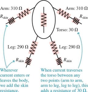
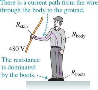
The human body can be modeled as a network of resistors. Skin resistance is much higher than internal body resistance, and protective equipment (e.g., rubber boots) greatly increases total resistance, reducing dangerous current flow.
Special Cases: Birds on Power Lines
Birds can safely perch on high-voltage lines because the potential difference between their feet is negligible, so little or no current flows through their bodies.
Ground Fault Interrupters (GFI)
GFI outlets detect differences between hot and neutral currents and disconnect the circuit if a ground fault is detected, providing enhanced safety in wet environments.
Summary Table: Key AC Circuit Quantities
Quantity | Symbol | Formula |
|---|---|---|
Peak voltage | Maximum value of AC voltage | |
RMS voltage | ||
Peak current | Maximum value of AC current | |
RMS current | ||
Average power |
Additional info:
Inductors and capacitors introduce reactance in AC circuits, causing phase differences between voltage and current (not covered in detail here).
Transformers only work with AC due to the need for changing magnetic flux.
