 Back
BackDC Circuits, Batteries, and RC Circuits: Study Notes
Study Guide - Smart Notes
 Tailored notes based on your materials, expanded with key definitions, examples, and context.
DC Circuits and Circuit Elements
Basic Circuit Components
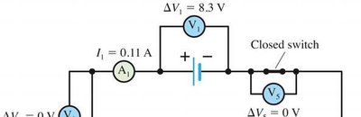
DC circuits are composed of batteries (voltage sources), resistors, switches, and measuring devices such as voltmeters and ammeters. Understanding how these elements interact is fundamental to circuit analysis.
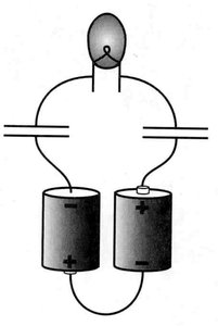
Batteries: Provide a constant electromotive force (emf) to drive current.
Resistors: Impede the flow of current, causing a voltage drop proportional to the current.
Voltmeters: Measure potential difference across components; connected in parallel.
Ammeters: Measure current through components; connected in series.
Real vs. Ideal Batteries
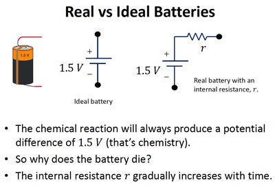
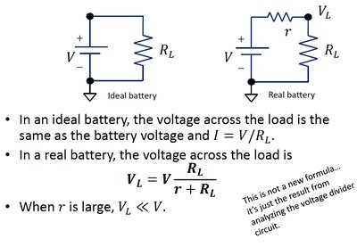
Batteries are modeled as ideal or real depending on whether internal resistance is considered. An ideal battery maintains a constant voltage regardless of current, while a real battery's voltage drops as internal resistance increases.
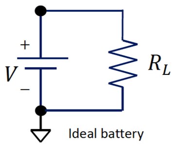
Ideal Battery: No internal resistance; voltage remains constant.
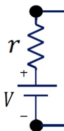
Real Battery: Has internal resistance r; voltage decreases as current increases.
Over time, r increases, causing the battery to 'die' even if the chemical reaction is not exhausted.
Voltage Across Load in Real and Ideal Batteries
The voltage across a load resistor R_L differs for ideal and real batteries. In real batteries, the internal resistance reduces the voltage available to the load.
For an ideal battery:
For a real battery:
When r is large,
Power Dissipation in Circuits
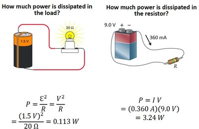
Power dissipated in resistors and loads is calculated using the voltage and current. This is a key concept for understanding energy transfer in circuits.
Power in a resistor:
Power using voltage:
Example: For a 1.5 V battery and 20 Ω resistor,
Voltage and Current Relationships
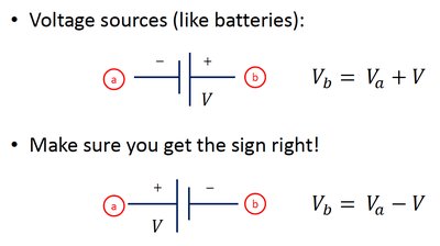
Voltage Sources
Voltage sources (batteries) add or subtract potential depending on the direction of traversal in the circuit.
Traversing from negative to positive:
Traversing from positive to negative:
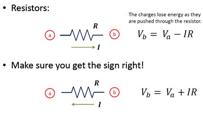
Resistors
Resistors cause a drop in potential proportional to the current and resistance. The sign depends on the direction of current relative to the points considered.
With current from a to b:
With current from b to a:
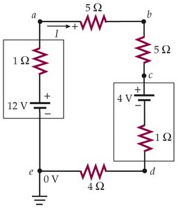
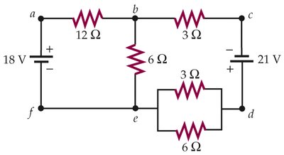
Kirchhoff's Rules and Circuit Analysis
Kirchhoff's Junction and Loop Rules
Kirchhoff's rules are fundamental for analyzing complex circuits:
Junction Rule: The sum of currents entering a junction equals the sum leaving it (conservation of charge).
Loop Rule: The sum of potential differences around any closed loop is zero (conservation of energy).
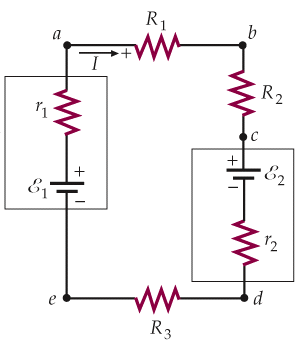
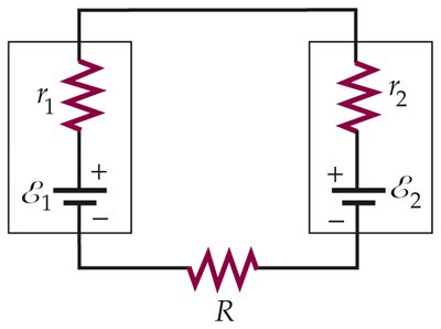
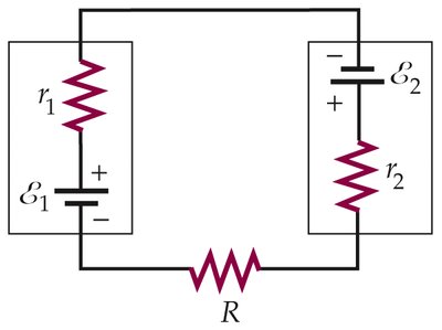
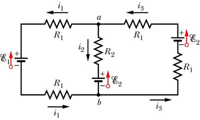
Multi-Loop Circuits
Multi-loop circuits require simultaneous application of Kirchhoff's rules to solve for unknown currents and voltages.
Assign current directions arbitrarily; negative results indicate opposite direction.
Write equations for each loop and junction; solve the system for unknowns.
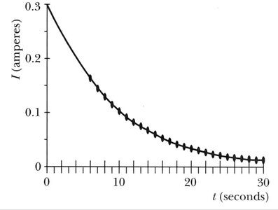
RC Circuits: Charging and Discharging
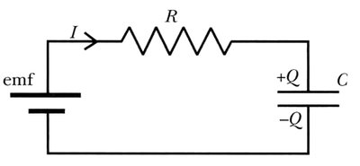
RC Circuit Fundamentals
An RC circuit consists of a resistor and capacitor connected in series with a voltage source. The charging and discharging of the capacitor follows exponential laws.
Current decreases exponentially as the capacitor charges.
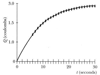
Charge on the capacitor increases exponentially, approaching a maximum value.
The time constant characterizes the rate of charging/discharging.
Mathematical Description
The current and charge in an RC circuit are given by:
Current: , where
Charge:
Voltage across capacitor:


RC Time Constant
The time constant is a measure of how quickly the circuit reaches equilibrium. After a time , the current drops to of its initial value.
At ,
At ,


Quantity | Formula | Description |
|---|---|---|
Current | Current decreases exponentially | |
Charge | Charge increases exponentially | |
Voltage | Voltage across capacitor | |
Time Constant | Characteristic time for charging/discharging |
Additional info: These notes expand on the original material by providing definitions, formulas, and context for each topic, ensuring completeness and academic clarity for exam preparation.
