 Back
BackElectric Circuits: Series and Parallel Circuits
Study Guide - Smart Notes
 Tailored notes based on your materials, expanded with key definitions, examples, and context.
Electric Circuits
Introduction to Electric Circuits
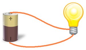
Electric circuits are fundamental to understanding how electrical energy is transferred and used in various devices. A circuit provides a path for electric current to flow, allowing energy to be delivered from a source to one or more loads.
Electric Current: The continuous flow of electric charges through a material. The unit of current is the ampere (A), which measures the amount of charge passing a point per second.
Basic Circuit Components: Most circuits consist of an energy source (such as a battery), one or more loads (such as bulbs or motors), and conductors (wires) connecting them.
Charge, Current, and Time
Current is defined as the rate of flow of electric charge. The relationship between charge (Q), current (I), and time (t) is given by:
Formula:
Units: Current (A), Charge (Coulombs, C), Time (seconds, s)
1 ampere (A) is equal to 1 coulomb of charge passing a point in 1 second.
Parts of a Circuit
Essential Components
Energy Source: Provides the push for charges to move (e.g., batteries, cells).
Load: A device that uses electrical energy (e.g., lamps, motors).
Conductor: Material that allows electric current to flow easily (e.g., copper wire).
Resistor: Limits the flow of current and causes a voltage drop. Measured in ohms (Ω).
Switch: Controls the flow of current by opening (off) or closing (on) the circuit.

Circuit Symbols
Standard symbols are used to represent components in circuit diagrams, such as:
Cell, Battery, Lamp, Switch, Resistor, Variable Resistor, Ammeter, Voltmeter, Fuse
Types of Circuits
Series Circuits
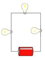
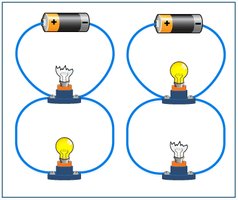
In a series circuit, all components are connected end-to-end, forming a single path for current to flow. If one component fails, the entire circuit is interrupted.
Current: The same at all points in the circuit.
Voltage: Divided among the loads.
Example: Old Christmas lights wired in series.

Mathematical Representation
(Current is the same everywhere)
Parallel Circuits
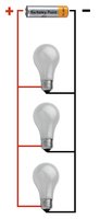
In a parallel circuit, components are connected across common points, providing multiple paths for current. If one component fails, others continue to operate.
Current: Splits among the branches; total current is the sum of branch currents.
Voltage: Same across each branch.
Example: Household wiring systems.
Mathematical Representation
(Total current is the sum of branch currents)
Comparing Series and Parallel Circuits
Property | Series Circuit | Parallel Circuit |
|---|---|---|
Current | Same through all components | Divided among branches |
Voltage | Divided among components | Same across each branch |
Effect of a break | All components stop working | Other branches continue to work |
Brightness of bulbs | Decreases as more bulbs are added | Remains the same as more bulbs are added |
Potential Difference (Voltage)
Definition and Measurement
Potential difference (voltage) is the energy transferred per unit charge as it moves between two points in a circuit. It is measured in volts (V) using a voltmeter, which must be connected across the component.
Formula: , where W is energy in joules (J) and Q is charge in coulombs (C).
1 volt = 1 joule per coulomb.
Voltage in Series and Parallel Circuits
Series: Voltage is divided among the loads.
Parallel: Each branch receives the full voltage of the source.
Ohm's Law and Resistors
Ohm's Law
Ohm's Law describes the relationship between voltage, current, and resistance in a circuit:
Formula:
Where V is voltage (V), I is current (A), and R is resistance (Ω).
Current is directly proportional to voltage for a constant resistance.
Resistors
Resistors oppose the flow of electric current, causing a voltage drop and dissipating energy as heat.
Increasing resistance decreases current for a given voltage.
Measuring Current and Voltage
Ammeter: Measures current and is connected in series with the component.
Voltmeter: Measures voltage and is connected in parallel across the component.
Applications and Real-World Examples
Household wiring uses parallel circuits to ensure devices operate independently.
Series circuits are used in some decorative lights, but have the disadvantage that one failure breaks the circuit.
Understanding circuits is essential for designing safe and efficient electrical systems.
Summary Table: Series vs. Parallel Circuits
Aspect | Series Circuit | Parallel Circuit |
|---|---|---|
Current | Same at all points | Divided among branches |
Voltage | Divided among components | Same across each branch |
Effect of a break | All components stop | Other branches continue |
Brightness of bulbs | Decreases with more bulbs | Remains the same |
Key Equations
Current:
Ohm's Law:
Series Circuit Current:
Parallel Circuit Current:
Practice Questions
Which type of circuit has only one path for current to flow? (Answer: Series circuit)
If one bulb burns out in a series circuit, what happens to the other bulbs? (Answer: They all turn off)
In a parallel circuit, what happens if one bulb burns out? (Answer: The other bulbs stay lit)
What is the unit of electric current? (Answer: Ampere, A)
How is voltage measured in a circuit? (Answer: Using a voltmeter connected across the component)
