 Back
BackElectric Power and Resistor Circuits
Study Guide - Smart Notes
 Tailored notes based on your materials, expanded with key definitions, examples, and context.
Electric Power and Circuits
Introduction to Electric Power
Electric power is a fundamental concept in physics and electrical engineering, describing the rate at which electrical energy is transferred by an electric circuit. Understanding electric power is essential for analyzing how energy is consumed and managed in various electrical devices and systems.
Electric Power (P): The rate at which electrical energy is converted to another form (such as heat, light, or mechanical energy) in a circuit element.
Formula: The basic formula for electric power in terms of voltage (V) and current (I) is:
Alternative Forms: Using Ohm's Law (), power can also be expressed as:
Units: The SI unit of power is the watt (W), where .
Applications: Electric power calculations are crucial for designing circuits, selecting components, and ensuring safety in electrical systems.
Resistor Circuits
Resistor circuits are foundational in understanding how current and voltage are distributed in electrical networks. Resistors can be arranged in series, parallel, or more complex combinations, affecting the overall resistance and power distribution.
Series Circuits: Resistors are connected end-to-end. The total resistance is the sum of individual resistances:
Parallel Circuits: Resistors are connected across the same two points. The reciprocal of the total resistance is the sum of reciprocals:
Example: Calculating the total resistance and power dissipated in a circuit with multiple resistors.
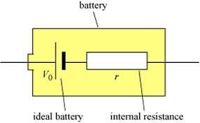
Internal Resistance of Batteries
Real batteries are not ideal voltage sources; they possess internal resistance, which affects the terminal voltage and the efficiency of energy delivery to external circuits.
Ideal Battery: Supplies a constant voltage regardless of the current drawn.
Internal Resistance (r): Represents the inherent resistance within the battery, causing a voltage drop as current flows.
Terminal Voltage: The voltage available to the external circuit is: where is the current.
Implication: As current increases, the terminal voltage decreases due to the internal resistance.
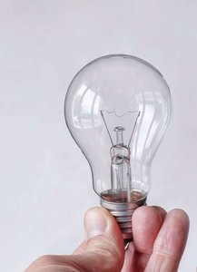
Applications: Light Bulbs and Power Dissipation
Light bulbs are common examples of resistive loads in circuits. The brightness of a bulb depends on the power dissipated in its filament, which is determined by the applied voltage and the resistance of the filament.
Power in a Bulb: The electrical energy is converted to light and heat, with power given by or .
Practical Consideration: The resistance of the filament changes with temperature, affecting the current and power.
Example: Calculating the power consumed by a 60 W bulb connected to a 120 V supply:
Combining Concepts: Circuit Analysis
Analyzing circuits often requires combining the concepts of electric power, resistance, and internal battery resistance. This allows for accurate predictions of current, voltage drops, and power dissipation in real-world circuits.
Step 1: Identify all sources of resistance, including internal battery resistance and external resistors.
Step 2: Use Ohm's Law and the power formulas to calculate current, voltage drops, and power dissipated in each component.
Step 3: Check for energy conservation: the total power supplied by the battery equals the sum of power dissipated in all resistive elements.
Summary Table: Key Formulas for Circuits
Quantity | Formula | Description |
|---|---|---|
Power (general) | Power delivered to a circuit element | |
Power (resistor) | Power dissipated in a resistor | |
Power (resistor) | Alternative form using voltage and resistance | |
Series resistance | Total resistance in series | |
Parallel resistance | Total resistance in parallel | |
Terminal voltage | Voltage across battery terminals with internal resistance |
Additional info: The images labeled image_1 and image_2 appear to be satellite or aerial images of a river delta or similar geographic feature and are not directly relevant to the physics of electric circuits, so they are not included. Only images directly illustrating circuit concepts or components (such as schematic diagrams or a light bulb) are used.
