 Back
BackElectric Power and Resistor Circuits: Study Notes
Study Guide - Smart Notes
 Tailored notes based on your materials, expanded with key definitions, examples, and context.
Electric Power and Resistor Circuits
Electric Power
Electric power is a measure of the rate at which electrical energy is transferred by an electric circuit. It is a fundamental concept in understanding how electrical devices consume energy and convert it into other forms such as heat, light, or mechanical work.
Definition: Electric power (P) is the rate at which electrical energy is delivered to a component or circuit.
Formula: The basic formula for electric power in terms of current (I) and voltage (V) is:
Alternative Forms: Using Ohm's Law (), power can also be expressed as:
Units: The SI unit of power is the watt (W), where .
Applications: Electric power calculations are essential for designing circuits, selecting components, and understanding energy consumption in devices such as light bulbs, heaters, and motors.
Resistor Circuits
Resistor circuits are foundational in physics and electrical engineering, as they illustrate how resistors affect current and voltage in a circuit. Understanding how to analyze these circuits is crucial for predicting circuit behavior and designing functional electronic systems.
Series Circuits: In a series circuit, resistors are connected end-to-end, and the same current flows through each resistor. The total resistance is the sum of individual resistances:
Parallel Circuits: In a parallel circuit, resistors are connected across the same two points, and the voltage across each resistor is the same. The reciprocal of the total resistance is the sum of the reciprocals of individual resistances:
Example: Calculating the equivalent resistance and power dissipated in a circuit with multiple resistors helps determine the current and voltage distribution.
Internal Resistance of a Battery
Real batteries are not ideal voltage sources; they possess internal resistance, which affects the terminal voltage and the power delivered to external circuits. Understanding internal resistance is important for accurate circuit analysis and for predicting battery performance under load.
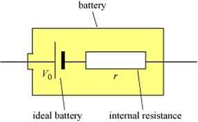
Model: A real battery can be modeled as an ideal voltage source () in series with an internal resistance ().
Terminal Voltage: The voltage available to the external circuit is reduced by the voltage drop across the internal resistance:
Power Delivered to Load: The power delivered to an external resistor () is: where
Implications: High internal resistance reduces the efficiency of power delivery, especially under high current loads.

Combining Concepts: Example Problem
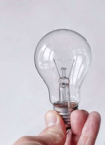
To solve real-world circuit problems, it is often necessary to combine the concepts of electric power, resistor circuits, and internal resistance. For example, determining the brightness of a light bulb in a circuit requires calculating the power dissipated in the bulb, considering both the external resistance and the internal resistance of the battery.
Step 1: Draw the circuit diagram, labeling all resistances and voltage sources.
Step 2: Calculate the equivalent resistance of the circuit.
Step 3: Use Ohm's Law and the power formulas to find current, voltage drops, and power dissipated in each component.
Step 4: Consider the effect of internal resistance on the terminal voltage and power delivered to the load.
Summary Table: Key Formulas for Electric Power and Resistor Circuits
Concept | Formula | Description |
|---|---|---|
Electric Power | General formula for power | |
Power (Ohm's Law) | Power in terms of current and resistance | |
Power (Voltage) | Power in terms of voltage and resistance | |
Series Resistance | Total resistance in series | |
Parallel Resistance | Total resistance in parallel | |
Terminal Voltage | Battery with internal resistance |
Additional info: The images of river deltas (image_1, image_2) are not directly relevant to the physics of electric circuits and are therefore excluded. The included images (image_3, image_4, image_5) directly illustrate battery internal resistance and electric power in a light bulb, supporting the explanations above.
