 Back
BackElectromagnetic Induction and Faraday’s Law: Study Notes
Study Guide - Smart Notes
 Tailored notes based on your materials, expanded with key definitions, examples, and context.
Electromagnetic Induction and Faraday’s Law
Induced EMF
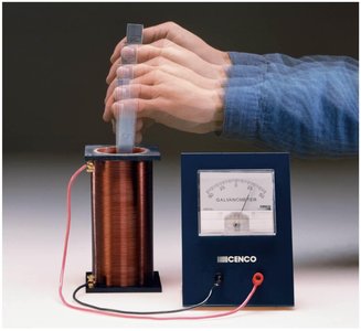
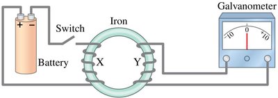
Electromagnetic induction is the process by which a changing magnetic field induces an electromotive force (emf) in a conductor. This phenomenon was first observed by Michael Faraday, who demonstrated that a current could be induced in a wire loop by changing the magnetic field through the loop.
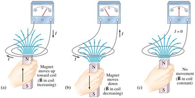
Key Point 1: A steady magnetic field does not induce an emf; only a changing magnetic field does.
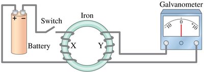
Key Point 2: The induced current is observed when the magnetic field changes, either by moving a magnet or by changing the current in a nearby coil.
Example: Moving a magnet through a coil induces a current, but holding the magnet steady does not.
Faraday’s Law of Induction and Lenz’s Law
Faraday’s Law states that the induced emf in a loop is proportional to the rate of change of magnetic flux through the loop. Lenz’s Law determines the direction of the induced emf, ensuring that the induced current opposes the change in magnetic flux.
Key Point 1: Magnetic flux (ΦB) is defined as the product of the magnetic field, the area it penetrates, and the cosine of the angle between the field and the area normal.
Key Point 2: The unit of magnetic flux is the weber (Wb), where 1 Wb = 1 T·m2.
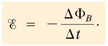
Key Point 3: Faraday’s Law (for a single loop):
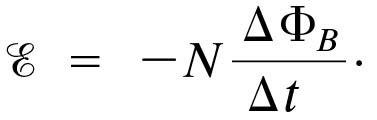
Key Point 4: For N loops:
Key Point 5: Lenz’s Law: The induced current creates a magnetic field that opposes the change in the original magnetic flux.
Example: If the magnetic flux through a loop increases, the induced current will flow in a direction that produces a magnetic field opposing the increase.
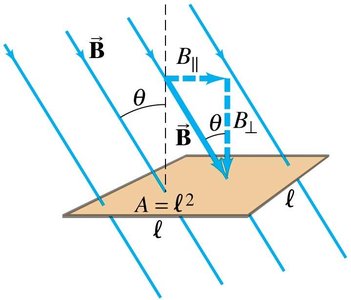
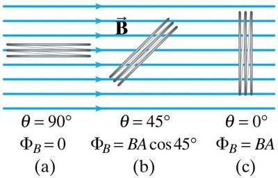
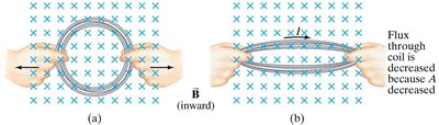
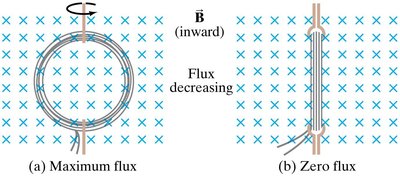
EMF Induced in a Moving Conductor
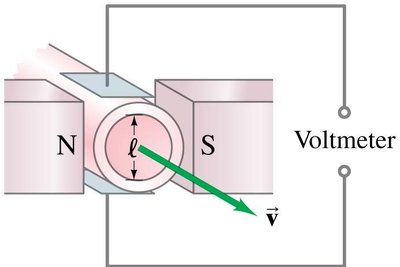
When a conductor moves through a magnetic field, an emf is induced across its ends. This is a direct consequence of the change in magnetic flux due to the motion of the conductor.
Key Point 1: The induced emf is given by: where B is the magnetic field strength, ℓ is the length of the conductor, and v is its velocity.
Key Point 2: The direction of the induced current is such that it opposes the motion (Lenz’s Law).
Example: Measurement of blood velocity using induced emf in a moving conductor.
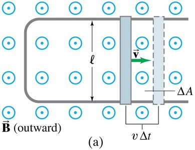
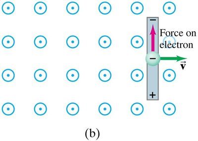

Changing Magnetic Flux Produces an Electric Field
A changing magnetic flux not only induces an emf in conductors but also produces an electric field in space, even in the absence of conductors. This is a generalization of Faraday’s Law and is fundamental to the operation of electromagnetic waves.
Key Point 1: The induced electric field is non-conservative and exists wherever the magnetic flux changes.
Example: The principle is used in electromagnetic wave propagation.
Electric Generators
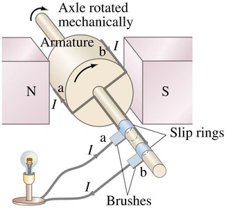
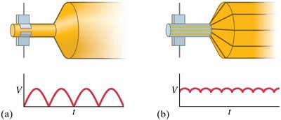
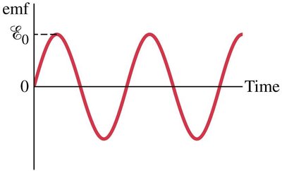
Electric generators convert mechanical energy into electrical energy by rotating a coil within a magnetic field. The induced emf is sinusoidal in alternating current (AC) generators, while direct current (DC) generators use a commutator to produce a unidirectional emf.
Key Point 1: AC generators use slip rings, while DC generators use split-ring commutators.
Key Point 2: The induced emf in a rotating loop is: where N is the number of turns, B is the magnetic field, A is the area, and ω is the angular velocity.
Example: Hydroelectric generators use falling water to rotate the coil.
Back EMF and Counter Torque; Eddy Currents
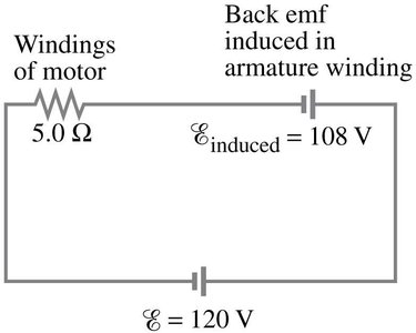
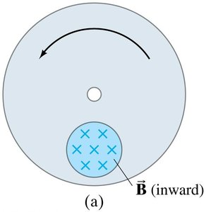
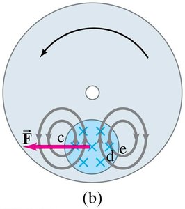
Back emf is the emf induced in a motor’s armature winding that opposes the applied voltage, creating a drag torque. Eddy currents are induced currents in bulk conductors, which can cause significant energy losses and slow down moving conductors.
Key Point 1: Back emf limits the acceleration of electric motors.
Key Point 2: Eddy currents are used in electromagnetic braking systems.
Example: Counter torque in generators requires increased external torque to maintain rotation.
Transformers and Transmission of Power
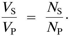
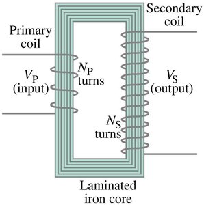
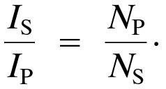
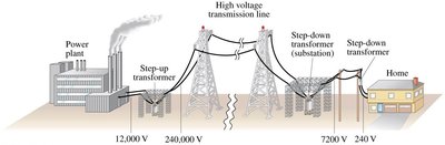
Transformers use electromagnetic induction to change the voltage of alternating current (AC). They consist of primary and secondary coils linked by an iron core. The ratio of voltages and currents is determined by the ratio of turns in each coil.
Key Point 1: Voltage ratio:
Key Point 2: Current ratio:
Key Point 3: Transformers only work with AC, not DC.
Example: Step-up transformers increase voltage for transmission; step-down transformers decrease voltage for safe use in homes.
Information Storage: Magnetic and Semiconductor; Tape, Hard Drive, RAM
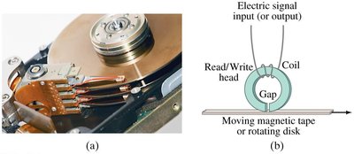
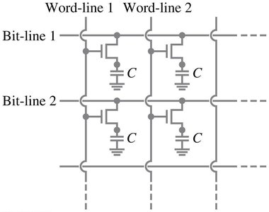
Information can be stored magnetically (tape, hard drives) or electronically (RAM). Magnetic storage uses ferromagnetic coatings to encode data, while RAM stores binary bits as electric charges or voltages.
Key Point 1: Magnetic tape and hard drives use magnetized regions to store data.
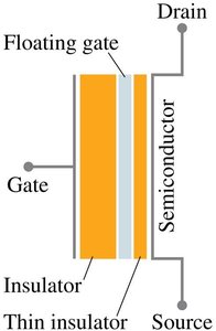
Key Point 2: RAM is volatile; it loses information when power is off. Nonvolatile memory retains data without power.
Example: DRAM uses MOSFETs to store bits; flash memory uses floating gate transistors for nonvolatile storage.
Applications of Induction: Microphone, Seismograph, GFCI
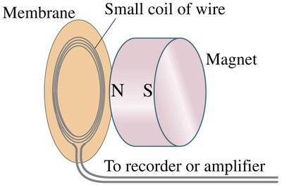
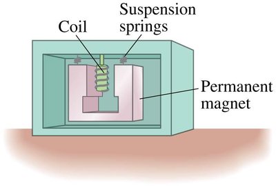
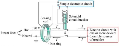
Electromagnetic induction is used in various devices, including microphones, seismographs, and ground fault circuit interrupters (GFCI).
Key Point 1: Microphones convert sound vibrations into electrical signals using induction.
Key Point 2: Seismographs detect earth movements by measuring induced currents.
Key Point 3: GFCIs protect against electrical faults by interrupting current flow when a fault is detected.
Example: Induction microphones are used in audio recording; GFCIs are standard in household electrical systems.
Inductance
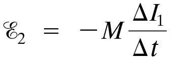
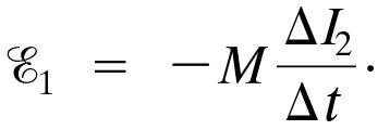
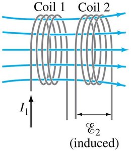
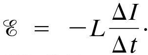
Inductance is the property of a circuit element (usually a coil) to oppose changes in current due to the induced emf. Mutual inductance occurs when a changing current in one coil induces an emf in another coil; self-inductance occurs when the emf is induced in the same coil.
Key Point 1: Mutual inductance equations:
Key Point 2: Self-inductance equation:
Key Point 3: Unit of inductance: henry (H), where 1 H = 1 V·s/A.
Example: Transformers are practical examples of mutual inductance.
Energy Stored in a Magnetic Field
Energy can be stored in a magnetic field, particularly in inductors. The energy density of a magnetic field is given by:
Key Point 1: Energy density equation: where B is the magnetic field strength and μ0 is the permeability of free space.
Example: Inductors in circuits store energy in their magnetic fields.

LR Circuit
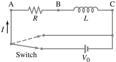
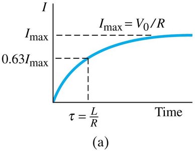
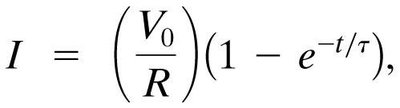
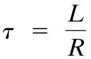
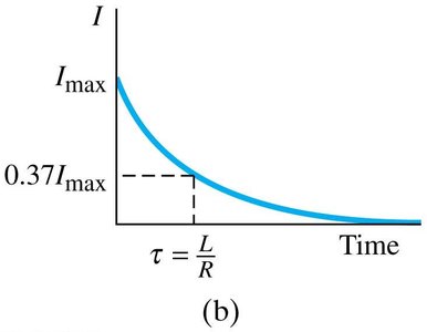
An LR circuit consists of an inductor and a resistor. When connected to a voltage source, the current increases gradually due to the inductor’s opposition to change. The time constant τ determines how quickly the current reaches its maximum value.
Key Point 1: Current growth equation: where
Key Point 2: When the circuit is shorted, the current decays exponentially.
Example: LR circuits are used in timing and filtering applications.
AC Circuits and Reactance
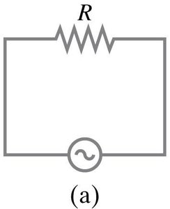
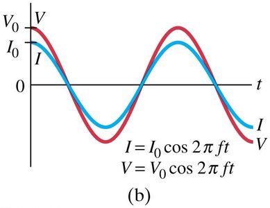
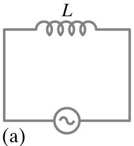
In AC circuits, resistors, capacitors, and inductors exhibit different phase relationships between current and voltage. The ratio of voltage to current for inductors and capacitors is called reactance, which depends on frequency.
Key Point 1: In resistors, current and voltage are in phase.
Key Point 2: In inductors, current lags voltage by 90°; in capacitors, current leads voltage by 90°.
Key Point 3: Reactance equations: Inductor: Capacitor:
Example: AC circuits are used in power transmission and signal processing.
LRC Series AC Circuit
The LRC series AC circuit contains a resistor, inductor, and capacitor. The voltages across each component are not in phase, so phasors (rotating vectors) are used to analyze the circuit. The impedance determines the effective resistance to AC.
Key Point 1: Impedance equation:
Key Point 2: The current is the same throughout the circuit.
Example: LRC circuits are used in radio tuning and signal filtering.
Resonance in AC Circuits
Resonance occurs in an LRC circuit when the inductive and capacitive reactances are equal, maximizing the rms current. The resonant frequency is given by:
Key Point 1: Resonant frequency equation:
Example: Resonance is used in radio receivers to select specific frequencies.
Summary Table: Key Concepts in Electromagnetic Induction
Concept | Equation | Unit |
|---|---|---|
Magnetic Flux | Weber (Wb) | |
Faraday's Law | Volt (V) | |
Mutual Inductance | Henry (H) | |
Self-Inductance | Henry (H) | |
Energy Density | J/m3 | |
Transformer Voltage Ratio | - | |
Transformer Current Ratio | - |
