 Back
BackElectromagnetic Induction and Inductance: Study Notes
Study Guide - Smart Notes
 Tailored notes based on your materials, expanded with key definitions, examples, and context.
Electromagnetic Induction
Introduction to Electromagnetic Induction
Electromagnetic induction is the process by which a changing magnetic field induces an electromotive force (emf) or current in a conductor. This fundamental principle underlies the operation of generators, transformers, and many other electrical devices.

Magnetic Flux
Magnetic flux (Φ) quantifies the total magnetic field passing through a given surface. It is defined analogously to electric flux and is measured in webers (Wb).
Formula:
Unit: 1 Wb = 1 T·m2
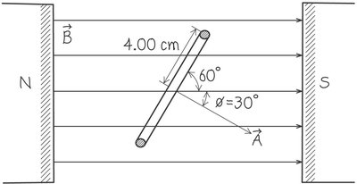
Vector Area: The direction of the area vector is perpendicular to the surface.
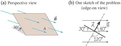
Example: For a surface of area 3.0 cm2 in a uniform magnetic field, the flux is +0.90 mWb. The area vector makes an angle of 30° with the field.
Induced Current and Faraday's Law
A changing magnetic flux induces a current in a closed loop. The induced emf is the voltage responsible for this current. Faraday's law quantifies this relationship:
Faraday's Law:
The negative sign indicates the direction of the induced emf (Lenz's law).
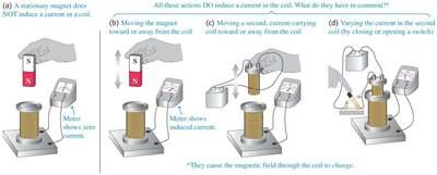
Key Point: Only changes in magnetic flux (not a stationary field) induce current.
Direction of Induced EMF (Lenz's Law)
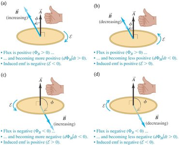
Lenz's law states that the induced current opposes the change in magnetic flux. The direction can be determined using the right-hand rule and the orientation of the area vector.
If flux increases, induced emf is negative.
If flux decreases, induced emf is positive.
Examples of Induced EMF and Current
Uniform Magnetic Field Increasing
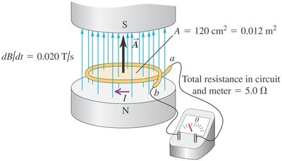
When the magnetic field between the poles of an electromagnet increases, the induced emf and current can be calculated using Faraday's law and Ohm's law.
Induced EMF:
Induced Current:
Coil in a Changing Magnetic Field
For a coil with N turns, the induced emf is multiplied by N. The direction of the induced current is determined by Lenz's law.
Formula:
Alternating Current (AC) and Generators
Alternators and generators produce alternating current (AC) by rotating coils in a magnetic field, causing the magnetic flux to change sinusoidally.
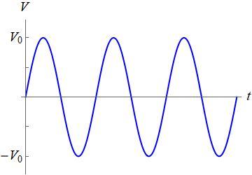
AC Voltage:
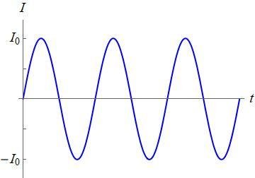
AC Current:
Peak Values: and are the maximum values.
Frequency: Most countries use 50 Hz or 60 Hz.
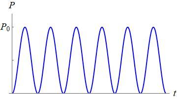
Power Dissipation: The average power in a resistor is given by where and are root-mean-square values.
Lenz's Law and Motional EMF
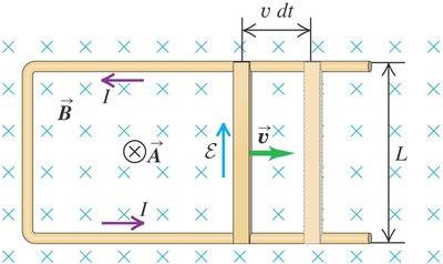
Lenz's law ensures that the induced current always opposes the change in magnetic flux. Motional emf is generated when a conductor moves through a magnetic field.
Motional EMF:
Induced Current:
Force on Rod:
Induced Electric Fields
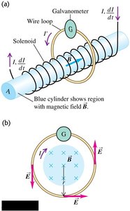
Changing magnetic flux induces electric fields, which can be described by Faraday's law in integral form:
Faraday's Law (Integral):
Eddy Currents
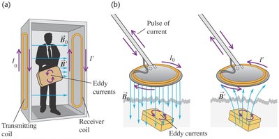
Eddy currents are loops of current induced within conductors by changing magnetic fields. They are used in applications such as metal detectors and braking systems.
Applications: Airport metal detectors, portable metal detectors.
Inductors and Inductance
Inductors
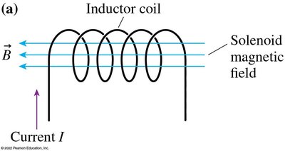
An inductor is a coil of wire that stores energy in its magnetic field. Any change in current through the coil induces an emf that opposes the change, according to Lenz's law.
Inductance (L):
Unit: Henry (H), where 1 H = 1 Wb/A
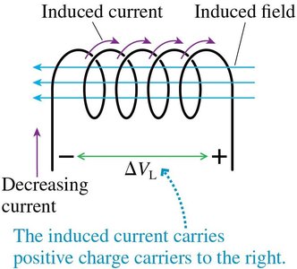
Potential Difference Across an Inductor
The potential difference across an inductor depends on the rate of change of current:
Formula:
If current increases, potential drops in the direction of current.
If current decreases, potential rises in the direction of current.
Energy Stored in Inductors
Inductors store energy in their magnetic fields. The energy stored is given by:
Formula:
Energy Density:
LC and LR Circuits
LC Circuits
An LC circuit consists of a capacitor and an inductor connected in a loop. Energy oscillates between the electric field of the capacitor and the magnetic field of the inductor.
Charge Oscillation:
Current Oscillation:
Angular Frequency:
LR Circuits
An LR circuit contains an inductor and a resistor. When the circuit is switched, the current decays exponentially due to the inductor's opposition to changes in current.
Current Decay:
Time Constant:
Example: If the switch is moved at t = 0, the current decays to 1% of its initial value after .
Additional info: The notes above expand on the original content with academic context, definitions, and formulas to ensure completeness and clarity for exam preparation.
