 Back
BackFundamentals of Circuits: Series, Parallel, and RC Circuits
Study Guide - Smart Notes
 Tailored notes based on your materials, expanded with key definitions, examples, and context.
Fundamentals of Circuits
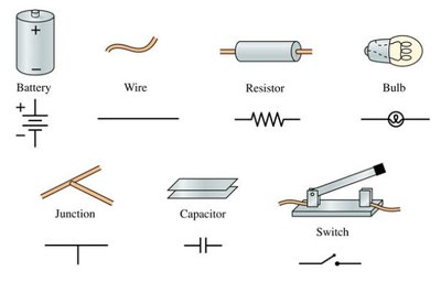
Symbols for Common Circuit Elements
Understanding circuit diagrams requires familiarity with the standard symbols used for various components. These symbols allow for concise representation and analysis of electrical circuits.
Battery: Provides electrical energy to the circuit.
Wire: Conducts current between components.
Resistor: Limits current and drops voltage.
Bulb: Converts electrical energy to light.
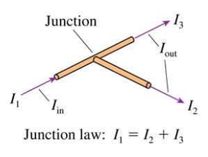
Junction: Point where wires meet; current can split or combine.
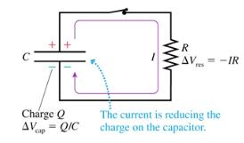
Capacitor: Stores electrical energy temporarily.
Switch: Opens or closes the circuit, controlling current flow.
Tools for Circuit Analysis
To analyze circuits, physicists use several fundamental laws and equations:
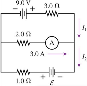
Kirchhoff’s Current Junction Law (KCL): The total current entering a junction equals the total current leaving it.
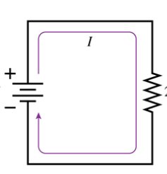
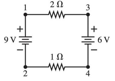
Kirchhoff’s Voltage Loop Law (KVL): The sum of voltage changes around any closed loop is zero.
Ohm’s Law: Relates voltage, current, and resistance:
Power in Circuits:
Series and Parallel Resistor Circuits
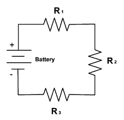
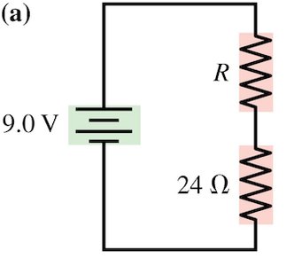
Series Circuits
In a series circuit, resistors are connected end-to-end, so the same current flows through each resistor. The total resistance is the sum of individual resistances.
Equivalent Resistance:
Current:
Voltage across each resistor:
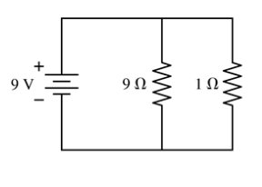
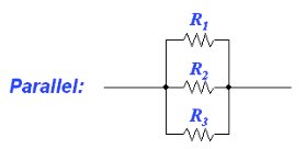
Parallel Circuits
In parallel circuits, resistors are connected across the same two points, so each resistor has the same voltage across it. The total resistance is found using the reciprocal formula.
Equivalent Resistance:
Current:
Current through each resistor:
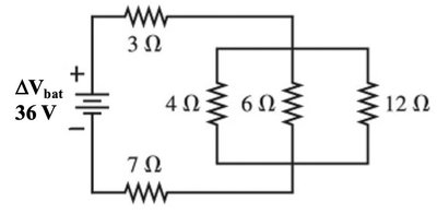
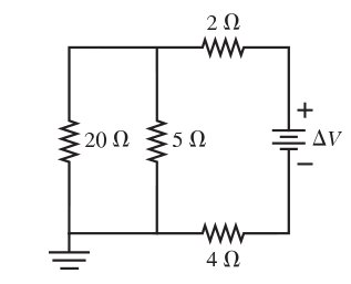
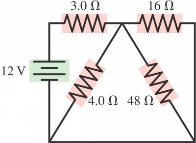
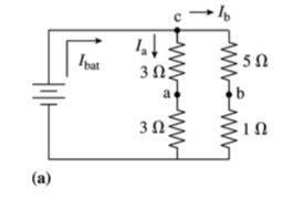
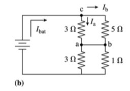
Combination Circuits
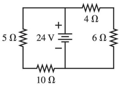
Some circuits contain both series and parallel elements. To analyze these, reduce the circuit stepwise by finding equivalent resistances for series and parallel groups.
Identify series and parallel sections.
Calculate equivalent resistances.
Apply Ohm’s Law and Kirchhoff’s Laws as needed.
Resistor and Capacitor Circuits (RC Circuits)
RC Circuit Basics
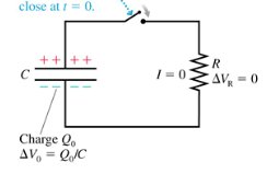
RC circuits combine resistors and capacitors. When a capacitor is charged or discharged through a resistor, the voltage and current change over time according to exponential laws.
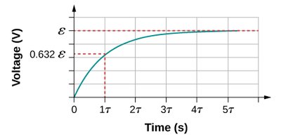
Charging:
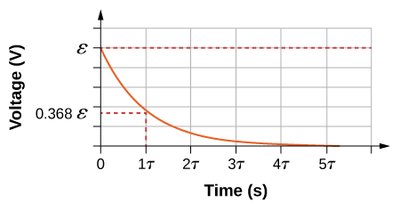
Discharging:
Time Constant:
Voltage across capacitor: (discharging)
Current:

Grounded Circuits
Electric Ground
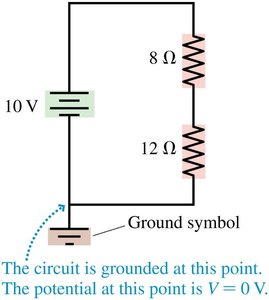
Grounding a circuit connects it to a reference point of zero voltage, called earth ground. This provides a common reference for measuring voltages and prevents unwanted voltage differences between circuits.
Ground symbol: Indicates the point in the circuit at .
Grounding does not affect circuit behavior: No current flows through the ground connection.
Real Batteries and Internal Resistance
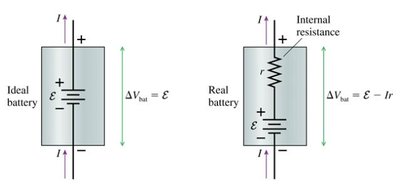
Ideal vs. Real Batteries
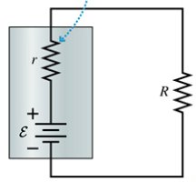
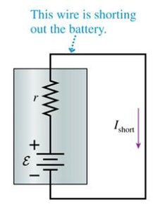
Real batteries have internal resistance, which reduces the voltage available to the circuit as current increases. The internal resistance increases as the battery discharges.
Ideal battery:
Real battery:
Equivalent resistance:
Voltage and Current Measurements
Voltmeter and Ammeter Usage
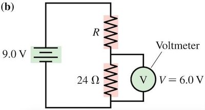
To measure voltage and current in circuits, voltmeters and ammeters are used. Their placement and resistance characteristics are crucial for accurate measurements.
Voltmeter: Connected in parallel; high resistance so negligible current flows through it.
Ammeter: Connected in series; very low resistance so it does not affect circuit current.
Example Problems
Series and Parallel Circuit Calculations
Applying the above principles, students can solve for current, voltage, and resistance in various circuit configurations.
Example 1: Find current in a series circuit with and .
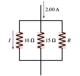
Example 2: Find current and voltage across resistors in a parallel circuit with , , and .
Example 3: Analyze combination circuits for equivalent resistance and current distribution.
Summary Table: Series vs. Parallel Circuits
Property | Series Circuit | Parallel Circuit |
|---|---|---|
Current | Same through all components | Splits among branches |
Voltage | Divided among components | Same across all branches |
Equivalent Resistance |
Additional info: These notes expand on brief points from the original materials, providing full academic context, definitions, and examples for self-contained study.
