 Back
BackInductors, Magnetic Fields, and Circuits – Step-by-Step Physics Guidance
Study Guide - Smart Notes
 Tailored notes based on your materials, expanded with key definitions, examples, and context.
Q1. The inductor in Fig. E30.9 has inductance 0.260 H and carries a current in the direction shown that is decreasing at a uniform rate, . (a) Find the self-induced emf. (b) Which end of the inductor, a or b, is at a higher potential?
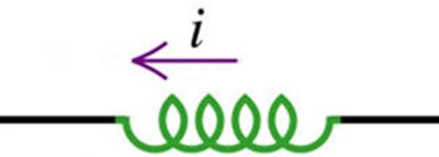
Background
Topic: Inductors and Electromagnetic Induction
This question tests your understanding of how inductors respond to changing currents, specifically how to calculate the self-induced emf and determine the relative potential at the ends of the inductor.
Key Terms and Formulas
Inductance (): A measure of an inductor's ability to oppose changes in current.
Self-induced emf (): The voltage generated across an inductor due to a changing current.
Key formula:
Step-by-Step Guidance
Identify the known values: , .
Recall the formula for self-induced emf: .
Plug the values into the formula, being careful with the sign of .
Consider the physical meaning: Since the current is decreasing, the induced emf will act to oppose this change (Lenz's Law).
Try solving on your own before revealing the answer!
Final Answer:
End 'a' is at a higher potential than end 'b' because the induced emf opposes the decrease in current, raising the potential at 'a'.
Q2. A resistor and an inductor are connected in series to a battery with emf 240 V and negligible internal resistance. The circuit is completed at time . At a later time the current is 5.00 A and is increasing at a rate of 20.0 A/s. After a long time the current in the circuit is 15.0 A. What is the value of , the time when the current is 5.00 A?
Background
Topic: RL Circuits and Time Constants
This question tests your ability to analyze the transient behavior of an RL circuit, including the calculation of time constants and the use of exponential functions to describe current growth.
Key Terms and Formulas
RL Circuit: A circuit with a resistor (R) and inductor (L) in series.
Time constant ():
Current growth:
Rate of change of current:
Step-by-Step Guidance
Identify the known values: , , , .
Use to solve for .
Use at to solve for .
Write the expression for and set to solve for .
Try solving on your own before revealing the answer!
Final Answer:
We used the exponential growth formula for current in an RL circuit and solved for the time when the current reaches 5.00 A.
Q3. Two very long insulated wires perpendicular to each other in the same plane carry currents as shown in Fig. E28.25. Find the magnitude of the net magnetic field these wires produce.
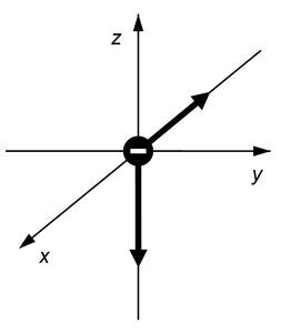
Background
Topic: Magnetic Fields from Current-Carrying Wires
This question tests your ability to calculate the magnetic field produced by multiple wires using the superposition principle and the Biot-Savart Law.
Key Terms and Formulas
Magnetic field from a long straight wire:
Superposition: Add vectorially the fields from each wire.
Step-by-Step Guidance
Identify the direction and magnitude of the magnetic field produced by each wire at the point of interest.
Calculate the magnetic field from each wire using .
Determine the vector directions of each field (use right-hand rule).
Add the fields vectorially to find the net magnetic field.
Try solving on your own before revealing the answer!
Final Answer:
The net magnetic field is , where and are the fields from each wire.
We used the Pythagorean theorem because the fields are perpendicular.
Q4. The diagram shows part of a circuit, with two inductors and one resistor in series. The potential at three points is indicated. What is the potential at point P?
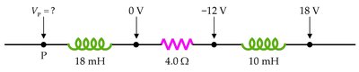
Background
Topic: Circuit Analysis with Inductors and Resistors
This question tests your ability to analyze potential differences in a circuit containing inductors and resistors, using Kirchhoff's rules and the concept of induced emf.
Key Terms and Formulas
Induced emf in an inductor:
Kirchhoff's Voltage Law: The sum of potential differences around a closed loop is zero.
Step-by-Step Guidance
Identify the known potentials at the three points and the values of the inductors and resistor.
Write the loop equation using Kirchhoff's Voltage Law, including the induced emfs and resistor voltage drop.
Express the potential at point P in terms of the other known potentials and the voltage drops across each element.
Set up the equation to solve for .
Try solving on your own before revealing the answer!
Final Answer:
We used the loop equation and the given potentials to solve for the unknown potential at point P.
Q5. Two very long uniform lines of charge are parallel and are separated by 0.300 m. Each line of charge has charge per unit length . What magnitude of force does one line of charge exert on a 0.0500 m section of the other line of charge?
Background
Topic: Electrostatics – Forces Between Line Charges
This question tests your ability to calculate the electrostatic force between two parallel lines of charge using Coulomb's Law and the concept of electric field from a line charge.
Key Terms and Formulas
Linear charge density (): Charge per unit length.
Electric field from a line charge:
Force:
Step-by-Step Guidance
Calculate the total charge on the 0.0500 m section: .
Find the electric field produced by the other line at the location of the first: .
Calculate the force: .
Plug in the values and set up the calculation.
Try solving on your own before revealing the answer!
Final Answer:
We calculated the force using the electric field from a line charge and the total charge on the segment.
Q6. When the current in a long, straight, air-filled solenoid is changing at the rate of 2000 A/s, the voltage across the solenoid is 0.600 V. The solenoid has 1200 turns and uniform cross-sectional area 25.0 mm2. What is the magnitude B of the magnetic field in the interior of the solenoid when the current in the solenoid is 3.00 A?
Background
Topic: Solenoids and Magnetic Fields
This question tests your ability to use the properties of solenoids to calculate inductance and the magnetic field inside the solenoid.
Key Terms and Formulas
Inductance of a solenoid:
Magnetic field inside a solenoid:
: Number of turns per unit length
Step-by-Step Guidance
Calculate the inductance using the given formula and values for , , and .
Find the number of turns per unit length .
Use to set up the calculation for the magnetic field.
Plug in the values for , , and .
Try solving on your own before revealing the answer!
Final Answer:
We used the formula for the magnetic field inside a solenoid and plugged in the calculated values.
