 Back
BackLecture 19
Study Guide - Smart Notes
 Tailored notes based on your materials, expanded with key definitions, examples, and context.
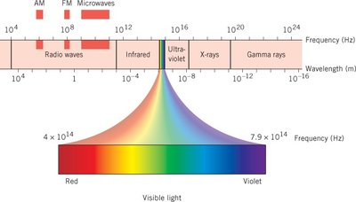
Interference and the Wave Nature of Light
Young’s Double-Slit Experiment
The double-slit experiment demonstrates the wave nature of light by producing an interference pattern of bright and dark fringes on a screen. When coherent light passes through two closely spaced slits, the light waves interfere constructively and destructively, creating a series of maxima and minima.
Constructive interference occurs when the path difference between the two waves is an integer multiple of the wavelength: , where
Destructive interference occurs when the path difference is a half-integer multiple of the wavelength:
Fringe spacing on the screen can be calculated using for small angles, where is the distance to the screen.
Example: For red light ( nm), slit separation m, and m, the distance to the third-order bright fringe can be found using the above equations.
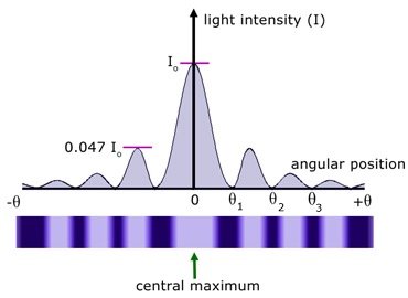
Single-Slit Diffraction
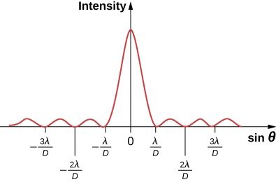
When light passes through a single narrow slit, it spreads out and forms a diffraction pattern with a central bright maximum and alternating dark and bright fringes. The intensity distribution is broader than for double-slit interference.
Condition for dark fringes: , where is the slit width and
Width of central maximum: , where
Effect of slit width: Narrower slits produce wider central maxima.
Example: For nm, m, and m, the width of the central bright fringe can be calculated.
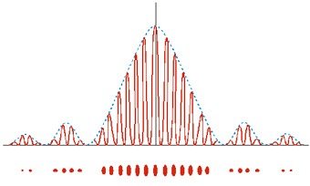
Double-Slit Interference Pattern with Diffraction Envelope
In a real double-slit experiment, the observed pattern is a combination of interference from the two slits and diffraction from the finite slit width. The result is a series of sharp interference fringes modulated by a broader single-slit diffraction envelope.
The envelope is determined by the single-slit diffraction pattern, while the fine structure is due to double-slit interference.
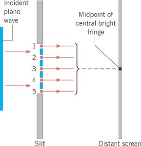
Huygens’ Principle and Diffraction
Huygens’ principle states that every point on a wavefront acts as a source of secondary spherical wavelets. The sum of these wavelets forms the new wavefront. This principle explains the spreading of waves through slits and around obstacles.
Destructive interference between wavelets leads to dark fringes in the diffraction pattern.
Diffraction Through a Circular Aperture
When light passes through a circular aperture, such as a small hole or the pupil of an eye, it forms a central bright spot (the Airy disk) surrounded by concentric rings. The angular position of the first minimum is given by:
, where is the diameter of the aperture.
This effect limits the resolving power of optical instruments.
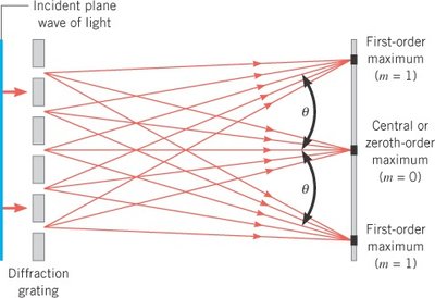
The Diffraction Grating
Principle and Equation
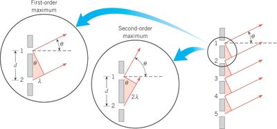
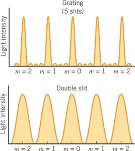
A diffraction grating consists of a large number of equally spaced parallel slits. When light passes through the grating, it produces sharp, narrow maxima at specific angles, allowing for precise measurement of wavelengths.
Principal maxima condition: , where is the distance between adjacent slits and is the order of the maximum.
Gratings produce much narrower and more widely separated maxima than double slits.
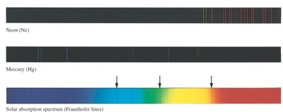
Applications: Spectroscopy and Line Spectra
Diffraction gratings are used in spectrometers to separate light into its component wavelengths, producing line spectra characteristic of different elements.
By measuring the angle for a known order and slit spacing , the wavelength can be determined.
Example: For a grating with lines/cm, the slit spacing is m.
Thin Film Interference
Principle and Phase Changes
Thin film interference occurs when light reflects off the upper and lower boundaries of a thin film, such as oil on water or soap bubbles. The two reflected waves can interfere constructively or destructively, depending on the film thickness, wavelength, and refractive indices.
A phase change of half a wavelength occurs upon reflection from a medium of higher refractive index.
No phase change occurs when reflecting from a medium of lower refractive index.
The condition for constructive or destructive interference depends on both the path difference and any phase changes upon reflection.
Calculating Film Thickness
Destructive interference (minimum reflected intensity): , where is the film thickness, is the refractive index of the film, and
Constructive interference (maximum reflected intensity):
Example: For gasoline () on water (), blue light ( nm) is eliminated by destructive interference, so the minimum nonzero thickness can be calculated.
Applications: Anti-Reflective Coatings
Thin films are used to minimize reflection from lenses by causing destructive interference for a specific wavelength. The optimal refractive index for the coating is given by Rayleigh’s equation: , where and are the refractive indices of the surrounding media.
The minimum thickness for destructive interference is .
X-Ray Diffraction
Principle and Bragg’s Law
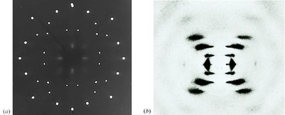
X-ray diffraction is used to study the atomic structure of crystals. When X-rays are incident on a crystal, they are scattered by the regularly spaced atoms, producing an interference pattern. The condition for constructive interference (Bragg’s Law) is:
, where is the spacing between crystal planes, is the angle of incidence, and is the order of the maximum.
This technique is crucial for determining crystal structures, such as NaCl and DNA.
Example: For X-rays of nm and a first maximum at , the spacing can be calculated.
Phenomenon | Key Equation | Application |
|---|---|---|
Double-slit interference | Measuring wavelength, interference patterns | |
Single-slit diffraction | Resolution limits, diffraction patterns | |
Diffraction grating | Spectroscopy, line spectra | |
Thin film interference | or | Soap bubbles, anti-reflective coatings |
X-ray diffraction | Crystal structure determination |
