 Back
BackPHYS 158 Study Guide: Introduction to DC Circuits and Circuit Elements
Study Guide - Smart Notes
 Tailored notes based on your materials, expanded with key definitions, examples, and context.
Course Overview
Introduction to PHYS 158: Electricity and Magnetism
This course covers fundamental concepts in electricity and magnetism, focusing on electric circuits, circuit elements, and their quantitative analysis. Students will learn to apply mathematical techniques and logical reasoning to solve problems involving electric currents, charges, and electromagnetic phenomena.
Key Topics: DC circuits, Kirchhoff’s Laws, capacitors, inductors, alternating current, electric fields, Gauss’s law, electric potential, magnetic fields, electromagnetic induction, and electromagnetic waves.
Learning Outcomes: Develop scientific thinking, understand abstract concepts (field, potential), and make quantitative predictions about circuit behavior.
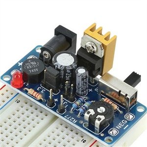
Basic Elements of DC Circuits
DC Circuit Components
DC circuits consist of several key elements, each with distinct roles in controlling and manipulating electric current and energy.
Resistor (R): Consumes electric power and limits current flow.
Capacitor (C): Stores and releases electric energy.
Inductor (L): Stabilizes current by opposing changes (creates induced current).
DC Power Supply/Battery (V or ε): Provides electric power to the circuit.
Switch (S): Alters the circuit's geometry, controlling current paths.
Light Bulb: Functions as a resistor.
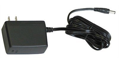
Power Supplies
Power supplies are essential for providing energy to circuits. They can be DC (direct current) or AC (alternating current).
DC Power Supply: Maintains a constant voltage and current direction.
AC Power Supply: Alternates voltage and current direction periodically.
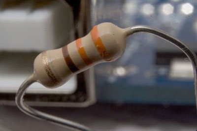
Resistors
Properties and Function
Resistors are devices designed to limit the magnitude of electric current and convert electrical energy into heat or light.
Function: Consumes electric power, limits current, and is used in devices like light bulbs.
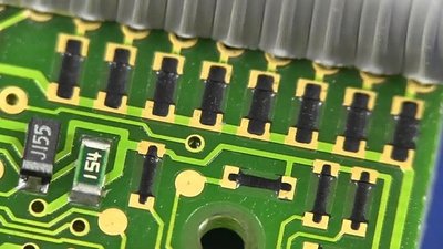
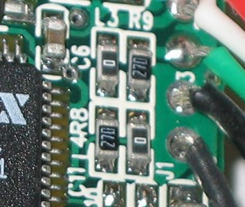
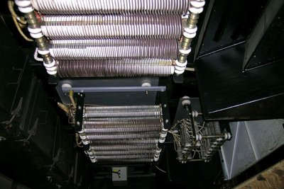
Physical Structure: Can be found in various forms, including wire-wound, surface-mount, and integrated circuit resistors.

Resistance and Material Properties
Resistance is a measure of how much a material opposes the flow of electric current. It depends on the material's resistivity (ρ), length (L), and cross-sectional area (A).
Formula:
Conductors: Low resistivity, support current (e.g., metals).
Insulators: High resistivity, do not support current (e.g., wood).
Semiconductors: Intermediate resistivity, properties change with temperature (e.g., Si, Ge).
Capacitors
Properties and Applications
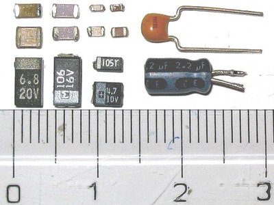
Capacitors are devices designed to store and release electric charge and energy. They are used in a wide range of applications, from electronics to medical devices.
Function: Stores energy in an electric field, releases energy quickly as a pulse.
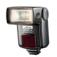
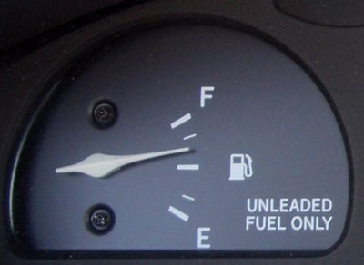
Applications: Touch screens, camera flashes, fuel gauges, defibrillators, keyboards.


Inductors
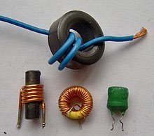
Properties and Function
Inductors are circuit elements that oppose changes in current by generating an induced electromotive force (EMF). They are used to stabilize current and filter signals.
Function: Opposes changes in current, creates "back EMF" proportional to the rate of change of current.
Formula:
Current, Resistance, and Voltage
Definitions and Relationships
Understanding the relationships between current, resistance, and voltage is fundamental to circuit analysis.
Current (I): Flow of positive charges, measured in amperes (A).
Resistance (R): Opposition to current flow, measured in ohms (Ω).
Voltage (V): Electric potential difference, measured in volts (V).
Ohm’s Law:
Voltage Drops Across Circuit Elements
Component-Specific Voltage Drops
Each circuit element has a characteristic voltage drop, which is essential for analyzing circuit behavior.
Resistor: (Ohm’s law)
Capacitor:
Inductor: (Back EMF)
Battery: EMF specified as or
Ohm’s Law and Equivalent Resistance
Application of Ohm’s Law
Ohm’s law applies to individual resistors, but circuits often contain multiple resistors. Equivalent resistance simplifies analysis by combining resistors into a single value.
Series Combination:
Parallel Combination:
Example: For resistors in series, the same current flows through each; for parallel, the same voltage is across each.
Complex Circuits
For circuits with combinations of series and parallel resistors, equivalent resistance can be calculated stepwise. Some circuits require advanced techniques beyond simple series/parallel rules.
Example Calculation: If , , : Series: Parallel:
Summary Table: Circuit Elements and Properties
Element | Symbol | Function | Voltage Drop |
|---|---|---|---|
Resistor | R | Limits current, consumes power | |
Capacitor | C | Stores/release energy | |
Inductor | L | Stabilizes current | |
Battery | V or ε | Supplies power | EMF specified |
Switch | S | Controls circuit geometry | N/A |
Additional info:
Some context and examples were inferred to ensure completeness and clarity for exam preparation.
