 Back
BackPhysics 153-1 Exam 2 Study Guidance: Circuits, Magnetism, and Capacitors
Study Guide - Smart Notes
 Tailored notes based on your materials, expanded with key definitions, examples, and context.
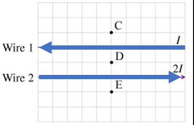
Q2. What is the direction of the magnetic field at Points C, D, and E near two parallel wires carrying currents?
Background
Topic: Magnetic Fields from Currents
This question tests your understanding of how magnetic fields are generated by currents in wires, and how to determine the direction of the field at specific points using the right-hand rule.
Key Terms and Formulas:
Right-Hand Rule: Used to determine the direction of the magnetic field around a current-carrying wire.
Magnetic Field from a Long Straight Wire:
= permeability of free space ( T·m/A)
= current in the wire
= perpendicular distance from the wire to the point
Step-by-Step Guidance
Identify the direction of current in each wire: Wire 1 has current to the left, Wire 2 has current to the right.
Apply the right-hand rule for each wire: For a wire, point your thumb in the direction of the current; your fingers curl in the direction of the magnetic field.
At each point (C, D, E), determine the direction of the magnetic field due to each wire separately.
Combine the contributions from both wires at each point to find the net direction of the magnetic field.
Try solving on your own before revealing the answer!
Final Answer:
Point C: points out of the page toward you.
Point D: points into the page away from you.
Point E: points into the page away from you.
These directions are determined by applying the right-hand rule to each wire and summing the fields at each point.
Q3(a). Simplify the circuit by finding the equivalent resistance for three resistors (, , ) connected to a capacitor.
Background
Topic: Series and Parallel Resistors
This question tests your ability to reduce a complex resistor network to a single equivalent resistance, which is essential for analyzing circuits.

Key Terms and Formulas:
Series Resistance: (if all are in series)
Parallel Resistance: (if all are in parallel)
Combination: Use both formulas if some resistors are in series and others in parallel.
Step-by-Step Guidance
Examine the circuit to determine which resistors are in series and which are in parallel.
If two resistors are in parallel, use to find their equivalent resistance.
Add the series resistor to the equivalent parallel resistance: .
Try solving on your own before revealing the answer!
Final Answer:
The equivalent resistance is found by first combining the parallel resistors, then adding the series resistor.
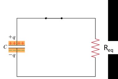
Q3(b). What is the direction of the current and electron flow after the switch is closed?
Background
Topic: Capacitor Discharge and Current Direction
This question tests your understanding of how current flows in a circuit when a capacitor discharges, and how electron flow relates to conventional current.
Key Terms:
Conventional Current: Flows from positive to negative terminal.
Electron Flow: Flows from negative to positive terminal (opposite to conventional current).
Step-by-Step Guidance
Identify the polarity of the capacitor: positive plate () and negative plate ().
When the switch is closed, current flows from the positive plate through the resistor to the negative plate.
Electron flow is opposite to the direction of conventional current.
Try solving on your own before revealing the answer!
Final Answer:
The conventional current flows from the positive plate of the capacitor through the resistor to the negative plate. Electron flow is in the opposite direction, from the negative plate to the positive plate.
Label these directions on the diagram as instructed.
