Back
BackLecture 15
Study Guide - Smart Notes
 Tailored notes based on your materials, expanded with key definitions, examples, and context.
Reflection of Light: Mirrors
Formation of Images by a Plane Mirror
The image formed by a plane (flat) mirror exhibits several distinct properties that are fundamental to understanding basic optics. These properties are essential for applications ranging from everyday mirrors to optical instruments.
Upright Image: The image appears upright, maintaining the same orientation as the object.
Same Size: The image is the same size as the object.
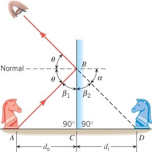
Equal Distance: The image appears as far behind the mirror as the object is in front of it.
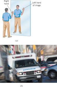
Left-Right Reversal: The image is reversed left-to-right. For example, your right hand appears as the left hand in the image.
Application Example: Emergency vehicles often have their lettering reversed so that it appears correctly in a driver's rear-view mirror.
Virtual Images in Plane Mirrors
When light rays reflect off a plane mirror, they appear to originate from a point behind the mirror. However, no actual light passes through this point; thus, the image is called a virtual image. Each point on an illuminated object emits rays in many directions, and the mirror reflects these rays according to the law of reflection.
Spherical Mirrors
Types of Spherical Mirrors
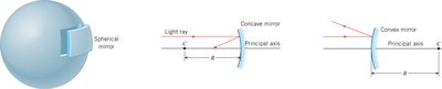
Spherical mirrors are segments of a sphere and come in two main types:
Concave Mirror: The inside surface is polished and reflective.
Convex Mirror: The outside surface is polished and reflective.
The principal axis is a straight line passing through the center of curvature (C) and the midpoint of the mirror. The radius of curvature (R) is the radius of the sphere from which the mirror is taken.
Focal Point and Focal Length
For a concave mirror, parallel rays near the principal axis converge at the focal point (F). The focal length (f) is the distance from the mirror to the focal point. For spherical mirrors, the focal length is related to the radius of curvature by:
For convex mirrors, the focal point is virtual and located behind the mirror. The sign convention assigns a negative focal length to convex mirrors.
Spherical Aberration
Not all rays parallel to the principal axis converge at a single point due to the spherical shape of the mirror. This effect is called spherical aberration. It can be minimized by using mirrors with small heights compared to their radius of curvature.
Ray Tracing for Spherical Mirrors
To locate the image formed by a spherical mirror, use the following principal rays:
Ray parallel to the principal axis reflects through the focal point (concave) or appears to diverge from the focal point (convex).
Ray passing through the focal point reflects parallel to the principal axis.
Ray passing through the center of curvature reflects back on itself.
The principle of reversibility states that if the direction of a light ray is reversed, it retraces its original path.
Image Formation by Concave Mirrors
The nature of the image depends on the object's position relative to the focal point (F) and center of curvature (C):
Object beyond C: Image is real, inverted, and reduced.
Object between F and C: Image is real, inverted, and magnified.
Object between F and mirror: Image is virtual, upright, and magnified.
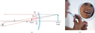
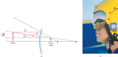
Image Formation by Convex Mirrors
For convex mirrors, the image is always virtual, upright, and reduced in size, regardless of the object's position.
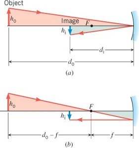
The Mirror Equation and Magnification
The quantitative relationship between object distance (), image distance (), and focal length () is given by the mirror equation:
The magnification (m) of the image is:
where is the object height and is the image height. The negative sign indicates an inverted image.
Sign Conventions for Spherical Mirrors
Focal length (f): Positive for concave, negative for convex mirrors.
Object distance (): Positive if object is in front of the mirror.
Image distance (): Positive for real images (in front), negative for virtual images (behind).
Magnification (m): Positive for upright images, negative for inverted images.
Refraction of Light: Lenses and Optical Instruments
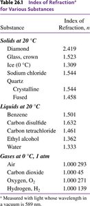
Index of Refraction
The index of refraction (n) of a material is the ratio of the speed of light in a vacuum () to the speed of light in the material ():
Light travels slower in materials with higher indices of refraction. The index of refraction varies for different substances.
Substance | Index of Refraction, n |
|---|---|
Diamond | 2.419 |
Glass, crown | 1.523 |
Ice (0°C) | 1.309 |
Water | 1.333 |
Air (0°C, 1 atm) | 1.000293 |
Oxygen | 1.000271 |
Hydrogen | 1.000139 |
Snell's Law and the Refraction of Light
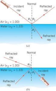
When light passes from one medium to another, it bends at the interface. The relationship between the angles and indices of refraction is given by Snell's Law:
where is the angle of incidence and is the angle of refraction.

Example: Determining the Angle of Refraction
Suppose a light ray strikes an air/water surface at an angle of 46° with respect to the normal. Using Snell's Law, the angle of refraction can be calculated for both directions (air to water and water to air).
From air to water: , ,
From water to air: , ,
Displacement of Light by a Slab
When a ray of light passes through a parallel-sided slab (e.g., glass), the emergent ray is parallel to the incident ray but displaced laterally. The angles of incidence and emergence are equal, but the path is shifted.
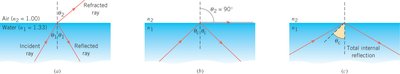
Total Internal Reflection
When light travels from a medium with a higher index of refraction to one with a lower index, the refracted ray bends away from the normal. If the angle of incidence exceeds a certain critical angle (), all the light is reflected back into the original medium—this is total internal reflection.
The critical angle is given by:
where .
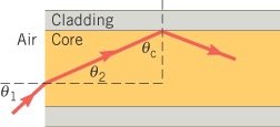
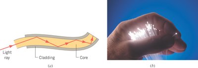
Applications: Optical Fibers
Optical fibers use total internal reflection to transmit light with minimal loss. The core of the fiber has a higher index of refraction than the cladding, ensuring that light reflects internally even when the fiber is curved. This principle is widely used in telecommunications and medical instruments.
Example: Critical Angle in Optical Fibers
Consider a fiber with a core of flint glass () and cladding of crown glass (). The critical angle for total internal reflection at the core-cladding interface is:

To find the maximum angle at which light can enter the fiber from air and still undergo total internal reflection, use Snell's Law at the air-core interface:
Given , , :