 Back
BackResistor Circuits and Kirchhoff’s Rules
Study Guide - Smart Notes
 Tailored notes based on your materials, expanded with key definitions, examples, and context.
Resistor Circuits
Resistor Connections
Resistors can be connected in different configurations within an electric circuit, primarily in series or parallel. The way resistors are connected affects the total resistance, current, and voltage distribution in the circuit.
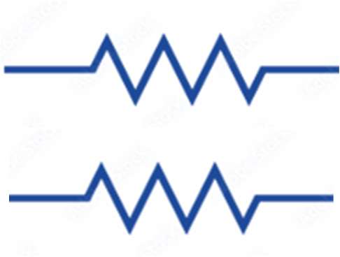
Resistors in Series
Properties of Series Connections
Negligible Wire Resistance: The resistance of connecting wires is assumed to be much smaller than that of the resistors themselves.
Same Current: The same current flows sequentially through each resistor in a series connection.
Definition: A series connection means that resistors are connected end-to-end, so there is only one path for current to flow.

Equivalent Resistance (Series):
The total or equivalent resistance of resistors in series is the sum of their individual resistances:
Example: If three resistors of 120 Ω, 360 Ω, and 90 Ω are connected in series, the total resistance is:

Resistors in Parallel
Properties of Parallel Connections
Negligible Wire Resistance: The resistance of connecting wires is negligible compared to the resistors.
Same Potential Difference: The ends of each resistor are connected to the same two points, so the voltage across each resistor is the same.
Different Currents: Each resistor may carry a different current, inversely proportional to its resistance.
Definition: A parallel connection means that resistors are connected across the same two points, providing multiple paths for current.
Current in Each Branch:
Total Current:
Equivalent Resistance (Parallel):
Example: If two resistors of 240 Ω each are connected in parallel, the equivalent resistance is:

Kirchhoff’s Rules
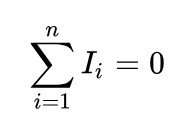
Kirchhoff’s Current Rule (Junction Rule)
This rule is based on the conservation of electric charge. It states that the sum of currents entering a junction equals the sum of currents leaving the junction:
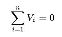
Kirchhoff’s Voltage Rule (Loop Rule)
This rule is based on the conservation of energy. It states that the sum of the potential differences (voltage) around any closed loop in a circuit is zero:
Battery’s Internal Resistance
Real vs. Ideal Batteries
Ideal Battery: Supplies a constant voltage regardless of the current drawn.
Real Battery: Has an internal resistance that causes a voltage drop when current flows.
Series Model: A real battery can be modeled as an ideal battery in series with a small resistor (the internal resistance).
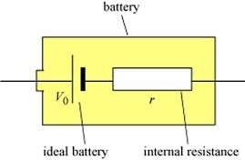
Terminal Voltage: The voltage across the battery’s terminals when supplying current is:
When the battery is not connected to a circuit (open circuit), and .
Summary Table: Series vs. Parallel Resistors
Property | Series | Parallel |
|---|---|---|
Current | Same through all resistors | Divided among branches |
Voltage | Divided among resistors | Same across all resistors |
Equivalent Resistance |
Additional info: The above notes include expanded academic context and examples for clarity and completeness.
