Back
BackResistors in Series and Parallel, and Battery Internal Resistance
Study Guide - Smart Notes
 Tailored notes based on your materials, expanded with key definitions, examples, and context.
Resistors in Series
Definition and Properties
When resistors are connected end-to-end so that the same current flows through each, they are said to be in series. This configuration is common in electrical circuits where components are arranged in a single path for current flow.
Negligible Wire Resistance: The resistance of connecting wires is assumed to be much smaller than that of the resistors themselves and is often neglected in calculations.
Current: The same current flows sequentially through each resistor in the series.
Equivalent Resistance: The total or equivalent resistance of resistors in series is the sum of their individual resistances.
Formula:
Example: If three resistors of 10 Ω, 20 Ω, and 30 Ω are connected in series, the total resistance is 60 Ω.

Resistors in Parallel
Definition and Properties
Resistors are in parallel when their ends are connected to the same two points, so the voltage across each resistor is the same. This configuration allows current to split and flow through multiple paths.
Negligible Wire Resistance: As with series, the resistance of connecting wires is neglected.
Voltage: The potential difference (voltage) across each resistor is the same.
Current: The total current is divided among the parallel branches, with each branch's current inversely proportional to its resistance.
Equivalent Resistance: The reciprocal of the equivalent resistance is the sum of the reciprocals of the individual resistances.
Formulas:
Example: If three resistors of 10 Ω, 20 Ω, and 30 Ω are connected in parallel, the equivalent resistance is:

Examples of Series and Parallel Combinations
Calculating Equivalent Resistance
Complex circuits often contain both series and parallel resistor combinations. To find the total resistance, reduce the circuit step by step, replacing series and parallel groups with their equivalent resistances.
Series Example: Two resistors of 120 Ω and 360 Ω in series:
Parallel Example: Two resistors of 240 Ω and 240 Ω in parallel:
Stepwise Reduction: For a combination of series and parallel resistors, first reduce parallel groups, then add series resistances.


Battery Internal Resistance
Real vs. Ideal Batteries
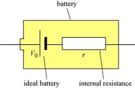
Real batteries are not perfect voltage sources; they have an internal resistance (usually denoted as r) in series with an ideal voltage source (V0). This internal resistance causes a voltage drop when current flows, reducing the terminal voltage available to the external circuit.
Current: The current through the battery and its internal resistance is the same as the current through the external circuit.
Open Circuit: When the battery is not connected to a load (open circuit), the terminal voltage equals the emf of the ideal battery, .
Loaded Circuit: When current flows, the terminal voltage drops by due to the internal resistance.
Formula:
Example: If a battery with and supplies , the terminal voltage is .