 Back
BackResistors in Series and Parallel, and Battery Internal Resistance
Study Guide - Smart Notes
 Tailored notes based on your materials, expanded with key definitions, examples, and context.
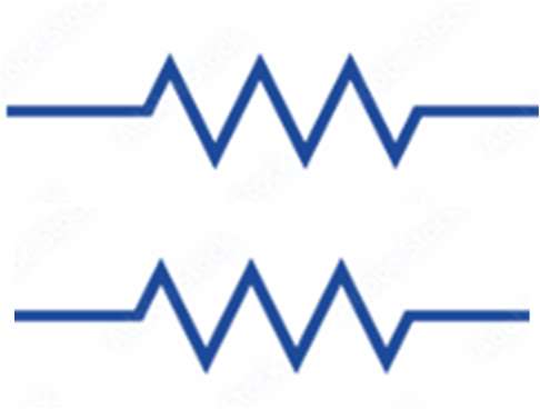
Resistors in Series
Definition and Properties
When resistors are connected end-to-end so that the same current flows through each, they are said to be in series. This configuration is fundamental in analyzing electric circuits.
Negligible Wire Resistance: The resistance of connecting wires is assumed to be negligible compared to the resistors themselves.
Current: The same current flows sequentially through each resistor in the series.
Equivalent Resistance: The total or equivalent resistance of resistors in series is the sum of their individual resistances.
Formula:
Example: If three resistors of 120 Ω, 360 Ω, and 90 Ω are connected in series, the equivalent resistance is:

Resistors in Parallel
Definition and Properties
When resistors are connected so that both ends of each resistor are connected to the same two points, they are in parallel. This arrangement is common in household wiring and many electronic devices.
Negligible Wire Resistance: The resistance of connecting wires is negligible.
Potential Difference: The voltage across each resistor is the same.
Current: The total current is divided among the parallel resistors, with each branch carrying a current inversely proportional to its resistance.
Equivalent Resistance: The reciprocal of the equivalent resistance is the sum of the reciprocals of the individual resistances.
Formulas:

Examples of Series and Parallel Combinations
Calculating Equivalent Resistance
Complex resistor networks can often be simplified by identifying series and parallel combinations and reducing them step by step.
Series Example: Three resistors of 120 Ω, 360 Ω, and 90 Ω in series have an equivalent resistance of 570 Ω.
Parallel Example: Two resistors of 240 Ω each in parallel have an equivalent resistance of 120 Ω.
Mixed Example: A combination of series and parallel resistors can be reduced by first simplifying the parallel parts, then adding series resistances.
Step-by-step reduction:
Identify and reduce parallel groups using the reciprocal formula.
Add series resistances directly.


Resistance of Coaxial Conductors
Core and Cladding
In coaxial cables, the core and cladding may have different resistivities. The total resistance depends on the geometry and the material properties of each region.
Core: The inner conductor, typically with lower resistivity.
Cladding: The outer conductor, which may have a different resistivity.
Formula for resistance of a cylindrical conductor:
where is resistivity, is length, and is cross-sectional area.
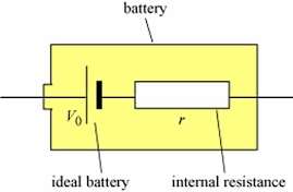
Battery Internal Resistance
Real vs. Ideal Batteries
Real batteries are not ideal voltage sources; they possess an internal resistance that affects the voltage delivered to a circuit when current flows.
Internal Resistance (): Represents the resistance inside the battery due to its materials and construction.
Voltage Drop: When current flows, the voltage across the battery's terminals is reduced by .
Open Circuit: If no current flows (open circuit), the terminal voltage equals the ideal emf .
Formula:
Example: If a battery with and supplies , the terminal voltage is:
Additional info: Understanding internal resistance is crucial for accurately predicting battery performance in real circuits, especially under high current loads.
