 Back
BackLecture 16
Study Guide - Smart Notes
 Tailored notes based on your materials, expanded with key definitions, examples, and context.
Snell’s Law and the Refraction of Light
Snell’s Law of Refraction
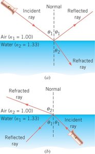
When light passes from one medium to another with a different index of refraction, its direction changes at the interface. This phenomenon is governed by Snell’s Law, which relates the angle of incidence and the angle of refraction to the indices of refraction of the two media.
Snell’s Law:
Index of Refraction (n): A measure of how much the speed of light is reduced in a medium compared to vacuum.
Angle of Incidence (\theta_1): The angle between the incident ray and the normal to the interface.
Angle of Refraction (\theta_2): The angle between the refracted ray and the normal.
When light strikes an interface, part of it is reflected and part is refracted (transmitted).
Example: Determining the Angle of Refraction
Consider a light ray striking an air/water surface at 46° with respect to the normal. Using Snell’s Law, the angle of refraction can be calculated for both directions:
From air to water: (air), (water),
From water to air: (water), (air),
Apply Snell’s Law to solve for in each case.

Total Internal Reflection
Critical Angle and Total Internal Reflection
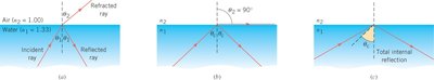
When light passes from a medium with a higher refractive index to one with a lower refractive index, the refracted ray bends away from the normal. If the angle of incidence exceeds a certain value called the critical angle, all the light is reflected back into the original medium—this is total internal reflection.
Critical Angle (\theta_c): The minimum angle of incidence for which total internal reflection occurs.
Formula: , where
For water/air interface:
For glass/air interface:
Applications: Used in prisms to turn light by 90° or 180°, and in optical instruments like binoculars.
Total Internal Reflection in Optical Fibers
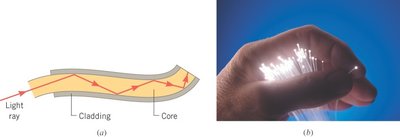
Optical fibers utilize total internal reflection to transmit light efficiently over long distances. The core of the fiber has a higher refractive index than the cladding, ensuring that light is reflected at the core-cladding interface.
Core: High refractive index material (e.g., flint glass)
Cladding: Lower refractive index material (e.g., crown glass)
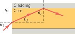
Light is totally reflected whenever it strikes the core-cladding interface at an angle greater than the critical angle.
Applications: Telecommunications, medical imaging, and illumination.
Example: Critical Angle in Optical Fiber
Given a fiber with a core of flint glass () and cladding of crown glass (), the critical angle and entry angle can be calculated:
Critical angle:
Entry angle from air: (using geometry and Snell’s Law)
Result:
Ray Tracing with Lenses
Lenses and Image Formation
Lenses refract light to form images. There are two main types: converging (convex) and diverging (concave) lenses. The focal length (f) is the distance from the lens to the focal point.
Converging lens: Paraxial rays parallel to the principal axis converge at the focal point.
Diverging lens: Paraxial rays appear to originate from the focal point on the same side as the object.
Thin lens approximation: Lens thickness is small compared to focal length.
Ray Diagrams for Lenses
Ray diagrams help determine the nature and position of images formed by lenses. For converging lenses:
Object beyond 2f: Real, inverted, smaller image (camera configuration).
Object between f and 2f: Real, inverted, larger image (projector configuration).
Object between f and lens: Virtual, upright, larger image (magnifying glass configuration).
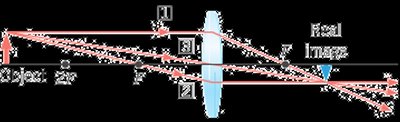
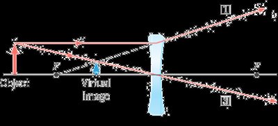
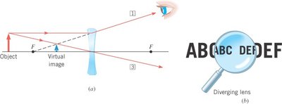
Image Formation by a Diverging Lens
A diverging lens always forms an upright, virtual, diminished image regardless of object position.
Virtual image: Appears on the same side as the object.
Image is always upright and smaller than the object.
The Thin-Lens Equation and Magnification
Equations and Sign Conventions
The thin-lens equation and magnification equation are used to calculate image position and size:
Thin-lens equation:
Magnification equation:
Sign conventions:
f is positive for converging lenses, negative for diverging lenses
d_o is positive if object is to the left of the lens
d_i is positive if image is to the right of the lens (real image), negative if to the left (virtual image)
m is positive for upright images, negative for inverted images
Example: Real Image Formed by a Camera Lens
A 1.70-m tall person stands 2.50 m in front of a camera with a converging lens of focal length 0.0500 m.
Image distance:
Magnification:
Image height:
Result: Real, inverted, reduced image.
Example: Virtual Image Formed by a Diverging Lens
An object is placed 7.10 cm to the left of a diverging lens with focal length -5.08 cm.
Image distance:
Magnification:
Result: Virtual, upright, reduced image.
Example: Two-Lens System
Two converging lenses, each with focal length 20 mm, are separated by 30 mm. An object is placed 28 mm in front of the first lens. The final image distance and magnification are found by sequentially applying the thin-lens equation and magnification formula for each lens.
Lens 1: Calculate
Lens 2: Use to find
Final magnification:
Result: Final image is inverted and reduced.
Summary Table: Sign Conventions for Lenses
Quantity | Converging Lens | Diverging Lens |
|---|---|---|
Focal Length (f) | + | - |
Object Distance (d_o) | + | + |
Image Distance (d_i) | + (real), - (virtual) | - (virtual) |
Magnification (m) | - (inverted), + (upright) | + (upright) |
Additional info: The notes cover topics from Chapter 23: Light: Geometric Optics, including Snell’s Law, refraction, total internal reflection, optical fibers, ray tracing with lenses, image formation, and the thin-lens equation. All images included directly reinforce the explanations and are relevant to the corresponding paragraphs.
